There are a few more items that must be taken care of before the tanks can be final riveted and then welded.
For the connections for the fuel lines, I bought some welding flanges with 1/4" pipe threads and finger screens with 1/4" pipe thread on the outside and 1/8" pipe threads on the inside. Since these flanges have a large diameter, I cut one side off to allow the fuel pickup to be as low in the tank as possible.
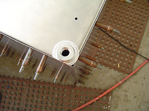
These will be welded to the front bottom corner and rear bottom corner of the root end of the tank. A hole was cut in each corner of the end rib on the tank as shown below.
Here is the welding flange in position:
I like the idea of having a fuel pick up at the front and aft ends so you in effect have two fuel pick ups for redundancy, and it doesn't matter if you are in a climb or a glide, you will have fuel fed to your engine (provided there is any fuel in the tank).
I have departed from the norm of the fuel level indicator. Most Bearhawkers are going with the sight tubes but I would rather have regular fuel gauges on my instrument panel. That's the nice thing about building your own airplane, you can build it to your own preferences.
I have decided to go with Mitchell instruments and purchased their universal fuel level sender (float type) and gauges. To mount the fuel level sender, a hole was cut as per the instructions that came with the sender unit. The hole was located 10" back from the leading edge of the fuel tank and centered of on the end rib at the root end of the tank.
The float has to be adjusted for length and bend until you get an accurate reading when the float is near the bottom, and near the top. I adjusted mine so that it reads empty when the float is about 1/8" off the bottom. To test it, the sender was wired up to one of the gauges and to the battery on my Jeep. Here is my test set up:
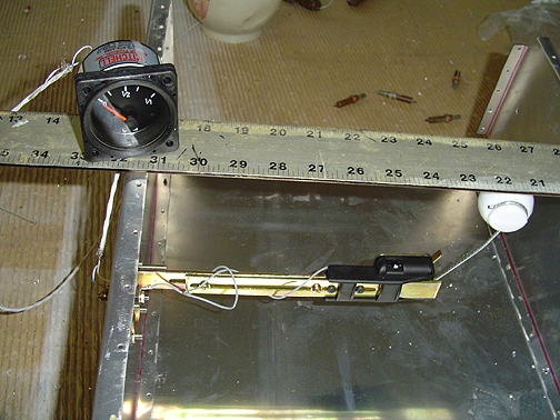
In the picture above, the tank is inverted and laying on it's top on the table. The bottom skin has been removed for access and a steel ruler was placed across the rib and baffle to simulate the tank bottom skin. As you can see, the float is in its bottom position and about 1/8" from the ruler simulating that the tank is nearly empty. The gauge reads 0 at this point.
I also tested the 1/2 full point by measuring from the ruler and setting the float at 3.5" from the bottom as shown here:
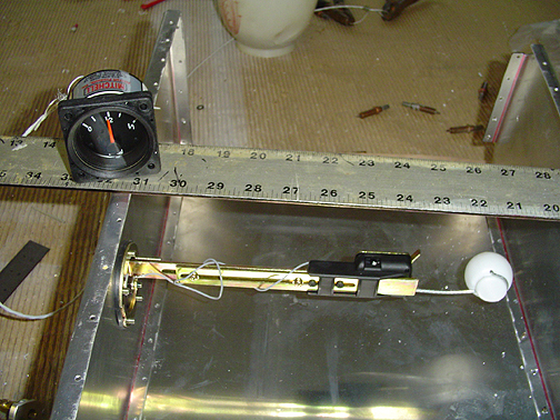
As you can see, the gauge now reads 1/2 full (or 1/2 empty for you pessimists).
Finally, the set up was tested with the float positioned against the top tank skin as shown below (again the the tank is inverted):
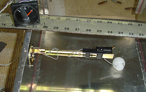
As you can see, the gauge reads 1/1 or full. It took quite a bit of fussing and bending to get the float at just the right length and bend angle to achieve this accuracy.
Russ Erb's CD indicates that some suggestion was made by the designer Bob Barrows, to bead the tanks near the baffle ribs to help alleviate some of the distortion during welding. About the time I read that, Harbor Freight tools had a 50% off sale and a nice 18" bead roller was on sale for $89.00 so I bought one. I can never pass up an opportunity to buy tools ;>)
Here is the business end of the bead roller:
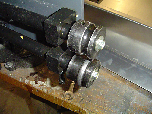
Tank skins top and bottom were bead rolled about 1 inch on either side of each baffle rib as shown below:
One thing that Russ pointed out was to have the top skins in the correct shape while beading them. If you bead them flat, it will create stress when you try to bend the top around the curve of the ribs/baffles. To accomplish this, I left the baffle clecoed to the skin while running the beads. When I was done, the baffles could be removed and the skin stayed curved in the shape of the baffles.
The tank was next riveted using solid and pull rivets. The solid rivets are 470A5-4. Notice they "A" and not "AD". These are a much softer rivet made from an alloy that is weldable. The pull rivets are AD52ABS (Wicks part #) which are 5/32 and made from 5052 aluminum (same as the tank skins) and have an aluminum mandrel instead of steel.
I was able to drive solid rivets for everything but the end ribs of the tanks. The baffles were positioned with their flanges facing outward and allowed me to drive solid rivets by leaving the end ribs out until the very end. The end ribs were then installed with pull rivets.
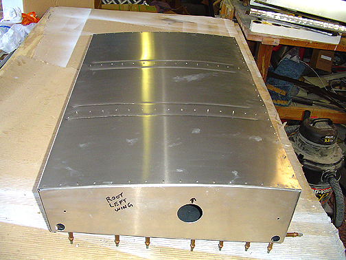
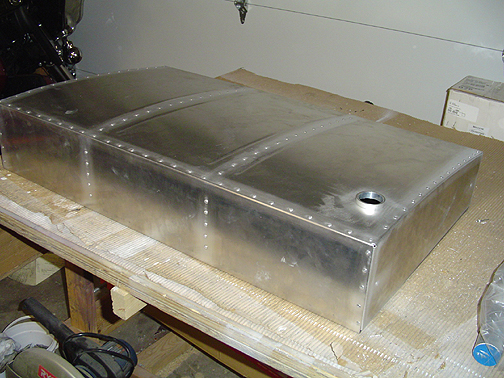
Here is one of the tanks all cleaned up (using a stainless steel brush) and ready for welding:
Notice the fuel filler flange in place. I have decided to go with the fuel filler flange and cap that Bob Barrows uses on the prototypes. I will cover how these were made on the Fuel Filler Cap page.
Click here to go to Fuel tanks page 3
Click here to go back to Fuel tanks page 1
Click here to go to the Wings Index page
Click here to go to the Home Page