The tanks were welded by my EAA Tech counselor and mentor Mickey Whittenburg. Mickey used a TIG welder with Argon gas. The welding took much longer than I had anticipated. These are some large tanks with long seams and many rivets. It took Mickey about 8 hours total to weld one tank.
note: Mickey has requested that I use rivets only in the baffles on the next tank, and just leave all of the other holes with clecos. He said that welding the holes shut is much easier than having to weld all of these rivets.
Once the tank was welded, it was tested for leaks as follows:
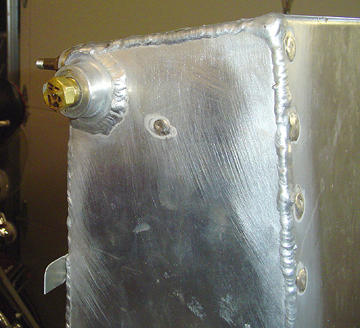
First the openings all had to be sealed. One of the flanges where the fuel lines will go was plugged using a standard pipe threaded brass plug from the hardware store:
To add air pressure, a tire valve with 1/8" pipe threads on one side, was located at the hardware store and installed where the drain petcock will be installed
The final bit of business is to figure out a way to regulate the air pressure in the tank. Really all you need is some positive pressure. You do not want more that about 1 to 1.5 P.S.I. in the tank.
When I built my RV, I used a very low tech method to regulate pressure in the tanks and it works great! As shown below, I used the same method involving a Balloon:
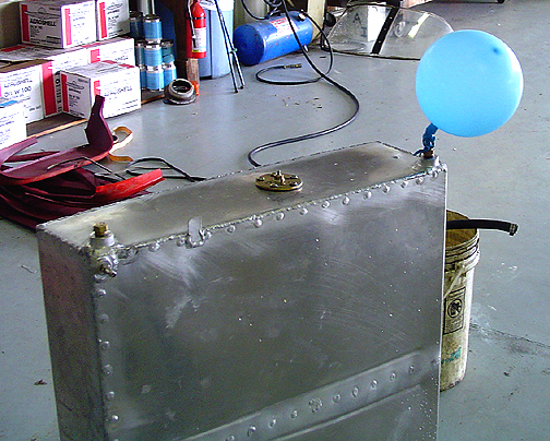
As you can see, my pressure regulator and safety valve is a balloon. That's right, a BALLOON. Its a great safety device, as I believe the balloon would pop long before any damage was done to the tank. At the hardware store I found a pipe thread plug with a hose barb sticking out. The balloon was attached to the barb with a rubber band.
Since I haven't made the Fuel filler cap yet, the filler neck was sealed off using several layers of duct tape and a hose clamp wrapped around the lip of the filler flange and tightened down to hold the duct tape in place and keep it from blowing off.
Air pressure was very gradually pumped into the tank through the tire valve until the balloon started to inflate. It takes a while to equalize the pressure in the tank and all of a sudden the balloon starts inflating rapidly. As the tank is pressurized, it makes a lot of scary noises and groans quite a bit so don't be alarmed, that is normal. Think of all of the forces that will be acting on the tank when it has 300 lbs. of fuel in it and you are in turbulent air.
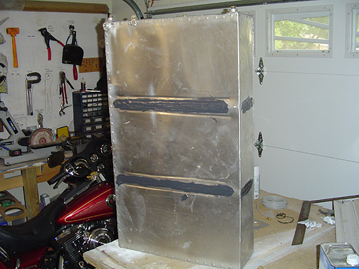
With the balloon happily inflated, all of the rivets and seams of the tank were sprayed liberally using a spray bottle filled with some Dawn dish soap mixed with water.
As expected, there were some leaks. A few leaks were from pin holes along the seams, but the leaks were most common were around the solid rivets. Funny, because I was thinking that the problem would be with the pull rivets but they actually sealed up nicely as did all of the seams.
The solid rivets were a different story, especially on the baffles. We kept re-welding and testing and re-welding and testing until they no longer created any bubbles. Why did the solid rivets have more leaks? Our theory was that that the solid rivets required quite a bit of heat to get them melted to flow. When the heat was taken away, the cooling was kind of sudden and uneven causing some rivets to crack or make a pin hole. The key was to try to gradually let off on the Tig welder pedal and let the arc die out slower. Even then the rivets wanted to crack at times causing a leak.
We finally got to point where there were no bubbles anywhere on the tank and the balloon stayed happily inflated for a long time. Even though there are no more leaks found, Mickey was a little concerned about those baffle rivets developing leaks later. The tank its likely to flex and move, with fuel being put in and burned off repeatedly for many cycles, especially around the baffles. He recommends that I put a coating of Proseal (fuel tank sealer) on just the baffle rivets for insurance. He says its kind of like wearing suspenders and a belt, you can never be too careful. I believe I will take his advise, just for my peace of mind.
The tanks are held in the wing with steel straps. The straps, in my case, are made from .025 thick 4130 steel plate that I had sheared into 1" strips by a local HVAC contractor on his 12 foot shear. The plans call for 2 straps across the top of the tank and three straps on the bottom of the tank. The straps are lined with some anti-chaffing material. I used some rubber channel purchased from Wicks that is designed for this purpose.
The top tank straps are not adjustable. The plans call for the top straps to be made to length just long enough to hold the fuel tank just slightly off (about 1/16") the skin stiffeners in the fuel tank bay of the wing. The bottom straps are fitted with strap tensioners as per the drawings.
Here are all the straps installed and waiting for the fuel tank:
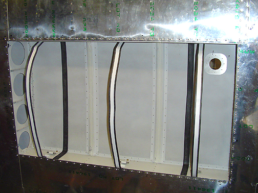
In the picture above, you can also see that I have installed a reinforcement piece around the opening in the top wing skin for the filler cap. The reinforcement plate is made from .062 aluminum to add thickness there.
Click here to go to Fuel Tanks (page 4)
Click here to go back to fuel Tanks (page 2)
Click here to go to the Wings Index page
Click here to go to the Home Page