Started June 12, 2004
I have done a lot of head scratching and pondering on the best way to handle the fuel filler caps on the tanks and the transition from tank to outer wing skin. There is a about a 5/16" to 3/8" gap between the top of the fuel tank and the outer wing skin. How do you fill that up and get it accurate with causing distortion in the wing skin?
I have decided to go with the Bob Barrows vented fuel caps that he uses on the prototypes. The drawings for the fuel filler caps and flange are located in the April 2000 Beartracks newsletter. His design is reminiscent of the old fashion thermos bottle cap that had a lever on it. You put the cap in the neck of the thermos and when you twisted the lever down, the cap sealed in the bottle by squishing the rubber seal out on the sides and against the inside of the thermos bottle neck.
Its a fun project if you have access to a lathe. Over the last few months, I have been learning to use the lathe over at Mickeys shop, and have been brushing up on my machining skills, so this was a great project for me and I was able to really learn a lot (and that's what this is all about for me).
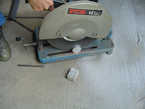
I started by purchasing a 2 foot long round bar of 6061T3 aluminum 2" diameter. I also purchased one that is 1.75" diameter.
To start with I made the filler flanges that will be welded into the tanks. This is part that the fuel cap goes into. Its is a very simple affair. I started by cutting off a piece of the round stock about 1/8" longer that needed:
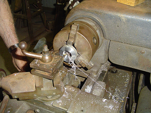
The piece was then placed in the lathe and machined to the proper dimensions:
Here is the the fuel filler cap flange that gets welded to the tank:
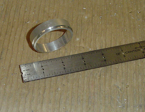
As you can see, there is lip that slips into the hole that is cut in the top of the fuel tank. It helps steady the filler cap flange during welding and keeps it centered in the hole.
The remaining parts were made one at a time, on the lathe, as per the drawings.
Here is a picture of top half of the filler cap that rests on the filler flange being turned in the lathe:
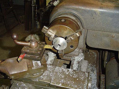
The center was drilled out 1/2" as per the specs and the outer ridges were turned to the dimensions given. The 1/2" hole is where the center piece of the fuel cap slips in place.
The center part of the filler cap is threaded on one end and has a wing shaped blade on the end that protrudes above the wing. I started by turning the piece with a 1" diameter, full length . The bottom end was then turned down to 1/2" and threaded with1/2" x 13 threads using a die. A groove for a small "O" ring was also turned into the 1/2" shaft.
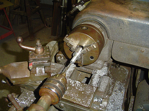
A hole is then drilled at the center, full length to within 1/8" of the very top of the piece. Here is a picture of the piece in the lathe with the hole being drilled in the center:
Once the bottom half was done, the top half needed to be made into the wing shaped flat blade. To do this we turned to the Bridgeport milling machine.
On a lathe the piece is turned and the cutting tool stays stationary. On a milling machine, its just the opposite. The piece is held stationary and the cutting tool spins.
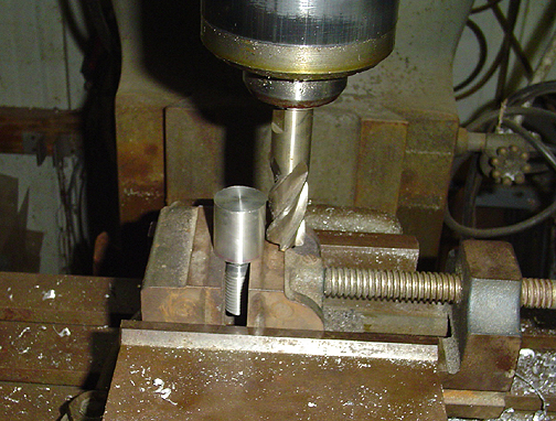
Here is a picture of the fuel cap center piece, clamped in place on the milling machine and ready to be cut:
The cutter spins and then is moved back and forth across the piece, taking about .010" off, on each pass. Our goal was to have a strip in the middle that is .20" wide as you will soon see.
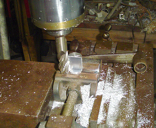
Here, one side had been cut and its time to reposition the piece to cut the other side:
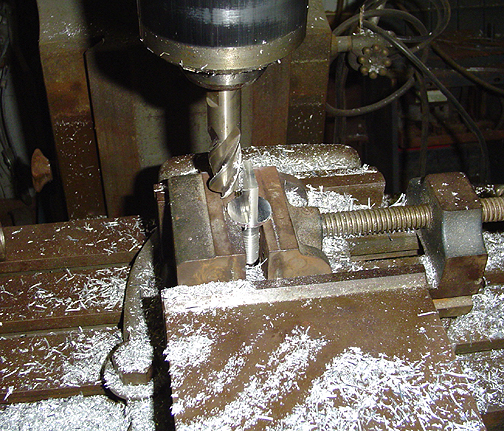
The other side was given the same treatment and here is the completed piece before final shaping:
Now a hole was drilled in the leading edge of this piece to meet with the other hole previously drilled.
Some filing and shaping were done next to fully radius the leading edge of the piece and to taper the aft end down to a 1/16" wide point. This was done in the the shape of an airfoil to lessen drag.
Here is a group shot of all of the pieces that comprise the vented fuel filler cap and flange:
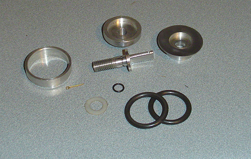
The "O" rings are "Viton". They are very long wearing and totally fuel resistant. The washer is nylon. You can also see a little cotter pin there. That is not originally listed in the parts list. That's because I made a small modification that I will explain after the next picture.
Here is the fuel cap assembled and ready to slip into the fuel flange (the part that's welded to the tank):
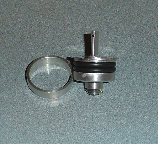
As you can see, I made the center piece about 1/4" longer than was called for in the plans. This is so the threaded portion protrudes down enough that I could drill a 1/16" hole and slip in a cotter pin. My fear is that an overly ambitious fuel line attendant will totally un-screw the cap and the bottom piece will simply fall into the tank. This will hopefully prevent that from happening. (note: I opened the vent hole in the cotter pin area to 3/16" to allow plenty of air to flow around the cotter pin).
That's 1 of 2 filler caps completed. I'll do the other one in the next few weeks and update this page with the total construction time then.
![]() Under Construction - check back later for
more. Last updated July 02, 2004
Under Construction - check back later for
more. Last updated July 02, 2004
Click here to go to Fuel Tanks page 2
Click here to go to Fuel Tanks page 3
Click here to go to Fuel Tanks page 4