To do the final installation of the fuel tank into the left wing, it was installed and shimmed up to the proper position for the fuel filler neck to line up with the hole in the wing skin.
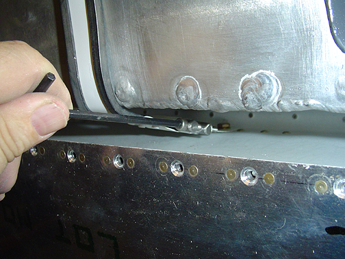
The strap tensioner bolts were then installed and tightened evenly , using an allen wrench as shown below:
How tight is tight enough? Tight enough so the tank can't be moved but not so tight as to crush the tank. Just before getting these tensioners tightened all the way down, a couple of drops of blue loctite thread locker was placed on the threads of these hex bolts to help prevent them from vibrating loose.
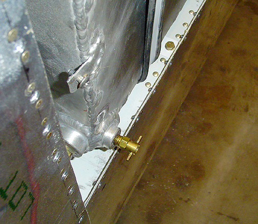
Here is the tank installed in the wing:
Here is a picture showing the fuel drain valve and just above it, you can see the tank grounding strap with a screw and platenut in it:
Here is the top side of the wing showing the fuel filler flange and vented fuel cap:
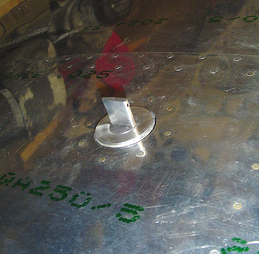
As previously stated, these fuel filler flanges are part of the Bob Barrows designed, vented fuel caps that I am making myself on a lathe. The fuel tank filler flange protrudes about 1/16" above the wing skin. I will later smooth in a small bead of Proseal to close the gap. I'll use some Proseal for this because it stays flexible but is also paintable.
The final bit of business is the tank cover plate for the wing bottom. The tank cover receives two hat section stiffeners just like the ones used for the wing skin in the fuel tank opening. The difference being that these were not curved to fit the curve of the wing, but were left flat.
The screw holes that were there from back drilling earlier (see skin page 4) were opening up to the proper size for a size 6 screw and then dimpled for the flush screws. I also located and drilled a hole for the tank drain valve.
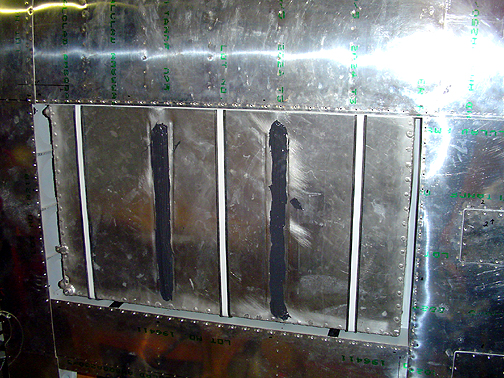
For now I have just installed the cover onto the wing with a half dozen screws. I didn't put in all of the screws because I still need to get in there when it comes time to run the fuel lines, fuel level sender wires, etc. Here is a pic with the tank cover in place on the left wing:
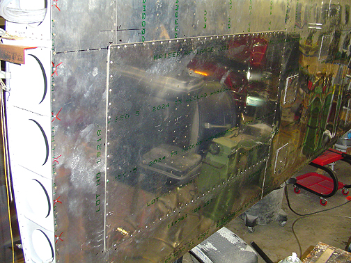
Its just loosely attached and will lay flush when all of the screws are installed and snugged down.
You can see the drain valve sticking out at the aft end of the tank cover. I really lucked out in positioning. The welding flange on the tank is just the right height that the cover skin rests on it and it doesn't protrude below the wing bottom. Only the drain valve itself sticks out.
Fuel Tanks (both)
Completed: October 15, 2004
Total Time: 112.5 hours