The Aileron Bellcrank consists of a piece of 3/4" tube, 7/8" long with two arms welded to it. The 3/4" tube must be machined with an inside "step" to receive a couple of round bearings to pivot on.
The ends on each arm of the Bellcrank receive some .125 (1/8") thick plate stock for bolting the cable ends to. The ends of each tube must be notched to receive the flat stock. I drilled a 1/8" hole in the tube, where I wanted the slot to end and then cut out the slot with a die grinder with a cutoff wheel.
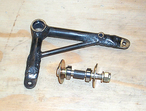
Here is a picture of a completed Aileron Bellcrank. Also pictured is the proper order of the bearings as they fit in the bellcrank:
As you can see in the picture above, there is a spacer between the bearings to support them. This must be fitted by grinding and checking, grinding and checking, on and on until it is the correct length. Too long and the bearings will not properly seat in the bellcrank tube, too short and the bearings receive no support and the side loads created on the bearing while tightening the bolt/nut will cause it to bind. The large area washers are a safety feature. If the bearings were to fail, hopefully the washers would contain everything enough to allow you to still have some control and get back to the airport.
Here is the aileron bellcrank and bearings assembly mounted on the aileron support frame:
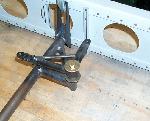
The bolt isn't quite long enough (I have the correct ones on order) so you can't see the bolt and nut sticking out through on the bottom.
Now I'll admit that I'm not the brightest guy around at times so it took me a lot of head scratching, looking at the plans, group archives, pictures of Bearhawks and Russ's CD to finally get a picture in my mind of out how the aileron control cables are routed. For those of you who don't know how it works, let me take some time here to explain it and save you a lot of research. The brighter of you might want to skip the next part because you already know how it works. The folks like me, will have a light bulb go off in their head.
Referring to the picture above - The arm that you see closest to the rear spar (the shorter of the two arms) has a 1/8" cable attached to it and runs parallel (more or less) with the rear spar, across the top of the fuselage and directly to the same arm on the aileron bellcrank of the other wing, in effect tying to the two bellcranks together. I believe there is a turnbuckle for tightening at the point where the bellcrank crosses the center of the fuselage top.
The second cable (also 1/8") attaches to the longer aileron bellcrank arm (with a turnbuckle), on its outer hole, runs parallel with the aileron support frame, toward the front of the wing. On the forward end of the aileron support frame there is a 3 1/2" pulley. The cable goes around this pulley, making a 90 degree turn and heads parallel with the main spar heading toward the wing lift strut. At the wing strut attach point of the wing, there is another pulley. The cable goes over that pulley and goes directly down the inside of the lift strut (which is hollow). At the bottom of the lift strut (where it attaches to the fuselage) there is another pulley. The cable then runs across to attach to the bottom of the control stick. The same on the other wing.
The only other thing is attaching the aileron bellcrank to the aileron itself. This is done via a pushrod which attaches to the top of the aileron hinge bracket. Pull on the pushrod, the aileron deflects upward, push on it and the aileron deflects downward.
So, tying it all together, and tightening the cables, here is how it works - this is long so stick with me- Moving the control stick to the left, the pulls the aileron control cable for the left wing, which pulls the left wing bellcrank, causing the aileron pushrod to be pulled back, which deflects the left wing aileron up. Meanwhile, the cable that stretches across the top of the fuselage, pulls the right wing bellcrank, which causes the right wing aileron bellcrank to rotate the opposite direction, pushing the aileron pushrod on the right wing defecting the aileron down.
Really an ingenious design. If you still can't picture it, I found that it helps to draw it all out on a piece of paper and using arrows you will see how it all ties together.
That's it for the Aileron Bellcranks. Now its on to the Flap Drive parts . . .
Click here to go to Flap Drive
Click here to go back to Aileron Drive Support Frame
Click here to go to the Wings Index page
Click here to go to the Home Page