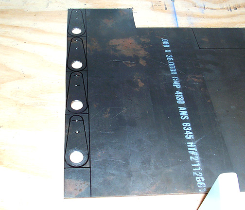
In all of the steel parts that I make, I always try to work with the largest pieces possible then final trim after the drilling and/or welding is done. Here is the layout for the 4 flap drive arms that are made from .080 steel plate:
The basic layout is drawn and the holes have been cut. I have found that the larger holes are easier to drill in a large sheet so I drilled those before cutting the individual parts out. The 3/4" holes were drilled with a hole saw and lots of cutting oil. The center hole is where the flap return spring attachment will be located.
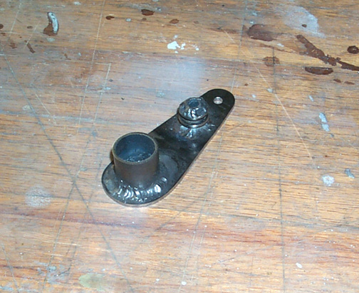
The flap return spring attachments were welded on first. Construction of these is like was done on the flap drive support frame. They are basically a piece of 3/8" tube, welded to the arm and some washers welded on with a 1/8" gap for the spring to rest in.
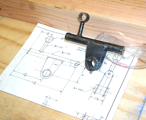
A piece of 7/8" tubing is welded on next. This must line up perfectly with the 3/4" hole so the Flap torque Tube can slid in. Once the 7/8" tube was final welded, the flap drive arm was cut and sanded to final shape as per the drawings. Here is one of the four flap arms:
The inside of the 7/8" tube was sanded with a dremel tool drum sander until a 3/4" tube would just barley slide on with some twisting and pushing. I wanted these to be a fairly snug fit so there is absolutely no slop at all.
Here is what the setup looks like mounted on the Flap Drive Support Frame with the flap return springs hooked up:
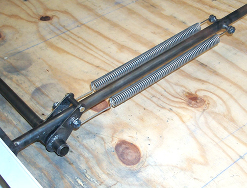
The springs are stainless steel and were purchased from Bob Barrows (R&B Aircraft). They are really nice and tight. It takes quite a bit of force to pull the flap drive back toward the rear spar. You can see that I have temporarily placed the drive tube cross piece and bushing in. The flap arm will be welded to the cross piece at a later time.
The flap arm at the root end of the wing was made next. It is a piece of .060 plate, bent to the shape shown, to form a ridged piece, which is then welded on to a piece of 7/8" tube as shown below
There is a left and right one so watch the plans. Here root flap drive arm welded to the end of the flap torque tube:
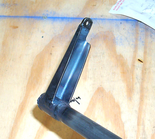
The difference in right and left is the length of the bent side. One is shorter to allow clearance for the flap drive cable travel.
Check that the flap drive arm is short enough to clear the aileron cable. You can check this by sliding the torque tube into the wing root support tube and using a piece of welding rod to simulate the aileron cable, hold it centered in the middle of the aileron cable support sticking straight out level. Move the flap drive arm back and forth to check that there is sufficient clearance. I had to shorten mine by 1/4".
That's it for Flap Drive parts. Next I'll work on the flap hinge mounts . . .
Click here to go to the Flap Hinges page
Click here to go back to Aileron Bellcrank