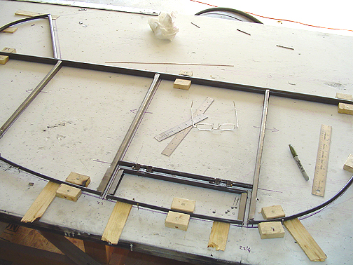
With the basic outline and the elevator laid out, wooden blocks were nailed to hold and support the tubing. This creates the jig.
Some discussion about the Trim Tabs before we go any
further:
While on a recent trip to Fincastle, VA, I took a long look at, and hundreds
of photos of, the two Prototype Bearhawks. I noticed on Proto 2 that
the trim tab was much shorter than shown on the plans. The plans show
the trim tab spanning across two ribs, however, on Proto 2, the trim tab
is only between the first and second elevator ribs.
I had a pretty long talk with Bob and told him of my plans to use an electric trim. We also discussed the fact that I would be, in all likelihood, installing the O-360 instead of the one of the heavier engines that most builders are going with. He said that the shorter trim tab was plenty long enough, and that especially with an electric trim, he would suggest that I go with the shorter trim tabs, to make it easier to over-ride a runaway trim condition, should that happen.
As a bonus, it makes construction easier as there are less variations in the T25 ribs.
Now that the elevator spar and trailing edge tubes are jigged in place, we can measure for and make the T-25 Ribs. To see how the T-25 ribs are made, click here and then come back to this page by clicking the "back" button on your browser, when you are done.
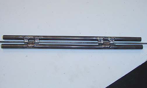
Here is the trim tab spars with hinges in place:
After cleaning out the welding scale with a long 3/16" bit, the trim spar tube can then be cut to the proper length to fit the trim tab and between the elevator ribs:
Now, before welding this up, I need to make the strap hinges that will be installed on the elevator spar. To see how those are made, click here and then return to this page by using the "back" button on your browser when you are finished.
Next, the elevator parts must be all cleaned up, properly positioned in the jig and welded.
The Strap hinges must be slid onto the elevator spar before welding. To allow the spar to lay flat on the table top, I used my router and cut some grooves in the plywood where the hinges are located. The grooves had to be deep enough to allow the grease fitting nut to lay in them as well.
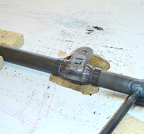
Notice in the above picture that the hinge retainer pieces are also slid onto the elevator spar. I will hold off on welding these to the spar until the elevators and Horizontal Stabilizers are fitted to the fuselage. That way I can make small adjustments, by sliding the elevator in or out. Once I'm happy with the final fit, these will be welded as per the plans.
Time to weld! Go to Elevators page 3 for that.
Click here to go to Elevators page 3
Click here to go back to Elevators page 1