Note that the tail support struts and tail wires have also been installed.
November 24, 2007
It is time to do the final assembly of the tail components. At this stage of the build process, I'm going to get very systematic. In other words, I plan to work on only one component at a time, finishing it before even looking at, or thinking about, the rest of the airplane. I will start at the tail and work my way forward, finishing each item completely before moving on.
At this point, any hardware store bolts that were used for mock-up purposes will now be replaced with fresh, new AN bolts (of the correct length), washers and nuts. Each nut will be properly torqued and will then receive a dollop of orange "torque seal". If it's a castle nut, it will receive a cotter pin and it will be properly cut and bent into position. In both cases, I know that the nut was properly torqued (or tightened) and hasn't moved since the last time I looked at it.
Final Assembly of the Tail Feathers
Before doing the final assembly of the horizontal stabilizers and elevators,
there were a couple of little chores I wanted to do while I still had good
access to the inside of the aft end of the fuselage. First, I re-checked
the torque on the bolt that holds the tail wheel spring to the fuselage and
put a cotter pin in it. Second, I completed the wiring splices for
the tail light, which is in the rudder and secured the wires. Lastly, all
bolts, nuts and wires on the electric trim servo were checked.
The rudder was already mounted during the painting stage so the stripes could be properly aligned. The tail light wires run through a couple of bushings that were welded into the rudder spar and tailpost. These were installed during fuselage construction.
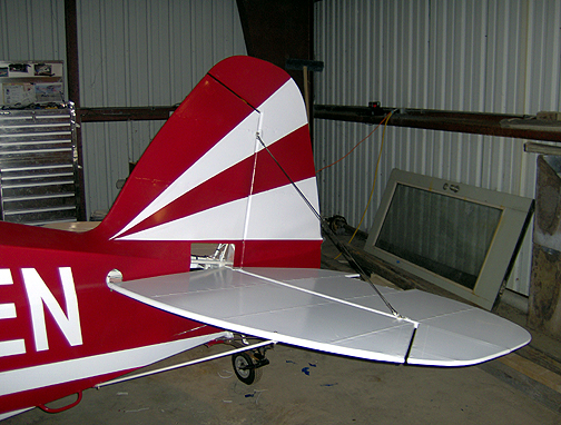
With those chores completed, the horizontal stabilizers and elevators were
installed and bolted in place:
Note that the tail support struts and tail wires have also been installed.
A quick word about the tail wires . . .
I chose to go with the stainless steel, streamline flying wires available
from Steen Aero Lab. These are fairly pricey, but have rolled threads
for safety and are cut to a streamline shape full length for less drag.
All of the research I've done on aerodynamic drag indicates that round
rods and tubes in the wind create an incredible amount of drag. Also
is the fact that Bob Barrows recommends buying the flying wires instead of
machining your own unless you are very experienced with how to cut threads
in a way that will not create a stress point in the rod (where the threads
begin on the rod). Since these are critical, I chose to purchase the
flying wires instead of attempting to make my own.
My tail wires are 46 1/8" for the top wires and 40 1/8" for the bottoms. These are the correct length if you have plans #455 or higher. In April 2000 there was an engineering change that relocated the elevator hinges outboard.
Back to the tail installation . . .
Here is the elevator horn area showing the hook-up of the elevator cables,
electric elevator trim system and rudder tail light and strobe wires:|
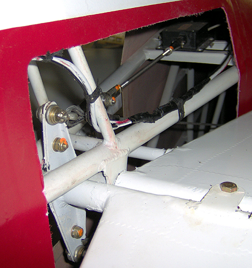
Again, I used a torque wrench to tighten each nut/bolt to the correct specs for the size used. As you can see in the above picture, there is a little spot of orange paint on each self locking nut. This is the product that I referred to earlier, called torque seal, available from Avery Tools. As each nut/bolt is torqued to specs, I put a little torque seal across the nut and bolt threads to let me know that nut/bolt was torqued. It will also let me know during later inspections if it has moved or loosened for some reason. I even look for it on any exposed nuts on the airplane during every pre-flight inspection.
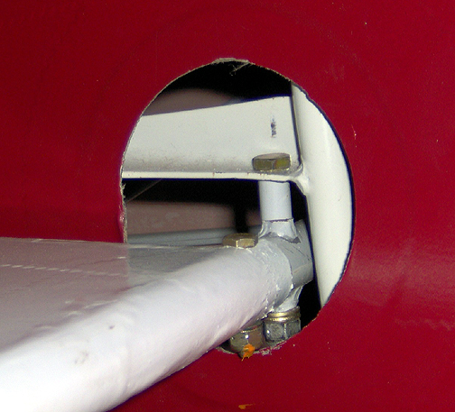
Here is the forward Horizontal Stabilizer mounted to the fuselage. I
could have located the hole in the fuselage a little better. I can
still access the bolts/nuts, but it would be a lot easier if the hole was
located better:
Here is the upper rudder hinge and tailwire fork rod end:
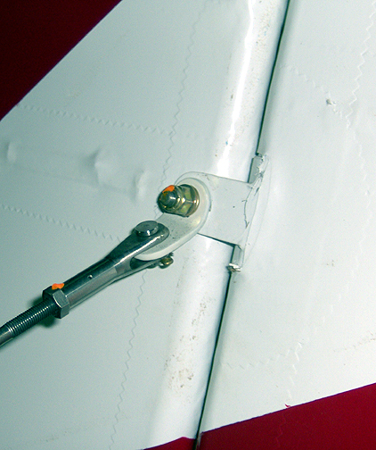
Note that I even dabbed a little orange torque seal on the tailwire fork
end jam nut. These will be checked during every pre-flight inspection
to assure nothing has moved or loosened. Also, did you notice
the little hole in the barrel of tailwire rod end? That hole is to
let you know whether or not you have an adequate amount of the tail wire
threads engaged in the rod end. You try to put a piece of .020 safety
wire in the hole. If it will not go in, you have enough
threads engaged. If the wire will go in, you need to fix
it.
Next the tailwheel steering springs were attached. I purchased the Maule
Anti-Shimmy Compression type springs (ACS P/N06-15150):
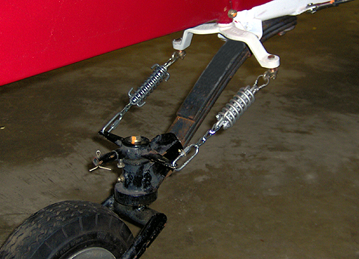
Note that the one on the right is larger and shorter than the one on the
left. This upsets the spring frequency, which in turn reduces the natural
tendency of the tailwheel to shimmy like a shopping cart wheel.
Here is a close-up of the connection at the rudder arm (ACS P/N 06-15900):
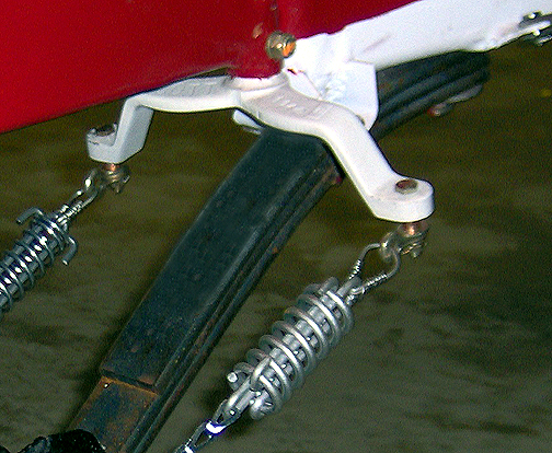
Note that I put a spacer on the bottom to allow the shackle to clear the
fork and have the ability to rotate. These were assembled using castle
nuts and cotter pins because they rotate.
Inspection Hole Covers
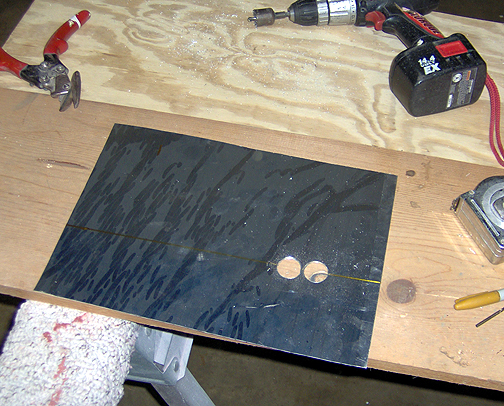
Next, I made the covers for the inspection holes at the aft end of the fuselage. This inspection hole was made fairly large, so I could reach the elevator cable hookups and electric trim system. The covers were made from .025" aluminum (2024T3)
I started by measuring the opening and made a cover that was about 1" too
large in each direction. I then figured out by measuring, exactly where
the centerline of the edge of the horizontal stabilizer will fall on this
cover plate. I want to split the cover and have the seam where the two halves
meet, to be hidden behind the horizontal stabilizer. A line was drawn
at the correct location. This will be cut in half at that line, but
first I want to make a provision for the horizontal stabilizer spar and elevator
torque tubes. These are each 7/8" diameter but I used a 1" hole saw
to cut two holes at the proper location as shown below:
The piece was then cut in half along the line to make a top half and a bottom
half. The top half was fitted first, bending along the line where the
upper longeron of the fuselage contacts the cover to make a proper fit.
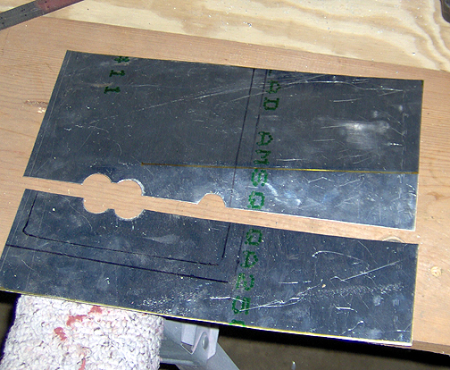
As you can see. I had to make another 1/2 hole in the top piece to fit
around the trim tab tube.
Click here to go to Final Assembly of the Tail page 2