I used 2" spacing for these holes. As you can see, the cover fits very nicely and should just about disappear once it's painted red. The edge of the cover was rolled ever so slightly using a seam roller.
The piece was bent and shaped until it fit the top half of the inspection
hole properly. It was then trimmed to final size and drilled to the metal
ring that was installed around the inspection hole while
covering the fuselage:
I used 2" spacing for these holes. As you can see, the cover
fits very nicely and should just about disappear once it's painted red.
The edge of the cover was rolled ever so slightly using a seam roller.
The bottom half was fitted next, using the remaining half of the cover plate.
It was much easier to fit as there are no bends:
I did have to notch around the trim tab tube on the bottom cover as
well.
The splice line where the top and bottom halves come together are mostly
hidden behind the edge of the horizontal stabilizer. The only splice
area exposed after we are finished is the area just aft of the elevator torque
tube. I decided to reinforce this area a bit by riveting on a piece
of .032" aluminum on the inside as shown here:
When the two halves are put together, this tab goes to the inside and gives
me something to attach the bottom cover to at the splice line. Here it as
after assembly and drilling:
As you can see, we now have a nice tight splice line.
The front of the horizontal stabilizer is mounted through a standard sized
inspection hole in the fuselage side. A round cover was fabricated
from some .025 aluminum and drilled to the aluminum ring which was installed
during covering of the fuselage.
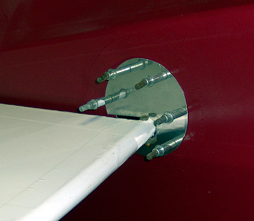
A slot had to be cut so the cover could be slid in place past the horizontal
stabilizer mounting tube. The slot is hidden behind the Horizontal
Stabilizer.
Gap Seal Fairings
Next, the gap seal fairings were made. These fairings simply seal the gap between the fuselage and the horizontal stabilizer.
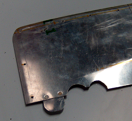
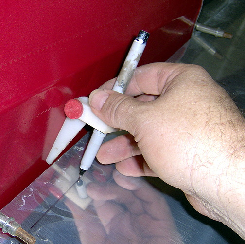
You will find that the fabric of the fuselage side curves in slightly where
the horizontal stabilizer meets it. To get the correct fit of the gap seal
fairing, the aluminum sheet (.032") was laid on top of the horizontal stabilizer
and held parallel with the inside edge of the horizontal stabilizer. Then
using a tracing marker, the shape of the fuselage side was transferred to
the aluminum:
The aluminum was then cut to shape and test fitted. It fit perfectly and was final trimmed to a width of 1 1/2" at its widest part.
The Horizontal Stabilizer inside rib was then pre-drilled on 2" centers. I found it easiest to pre-drill the horizontal stabilizer rib since it is so narrow and accuracy is important. I will use a strap duplicator (ACS P/N 12-01515) to match drill the holes to the gap seal fairing.
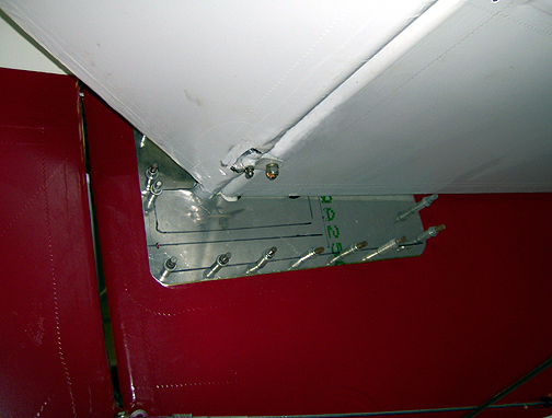
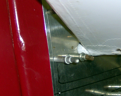
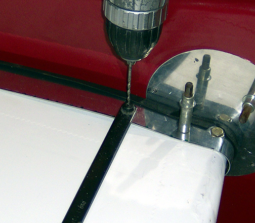
A hole is needed in the gap seal fairing to allow the forward horizontal
stabilizer bolt to slip through (see right side of picture below). Next the
"U" shaped rubber seal (ACS P/N 05-01400) was slipped on to the edge of the
gap seal fairing. The fairing piece was held snugly in place, pushing it
against the fuselage side, and it was match drilled to the holes in the
horizontal stabilizer using the strap duplicator:
Note: A strap duplicator has two strips of steel. The bottom one
has a punch which you place in the hole that was pre-drilled. The top strip
has a bushing with a hole in it perfectly aligned with the punch on the bottom
strip. When you drill through the bushing, the hole you make perfectly
aligns with the pre-drilled hole below.
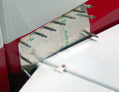
Here is the top gap seal fitted and drilled. I will use some #6 stainless
steel sheet metal screws to secure it to the stabilizer rib.
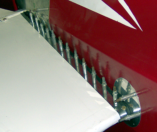
As you can see, the front edge of the strap curves around the leading edge
of the stabilizer. It will attach to the bottom gap seal fairing to
hold it snugly in place.
Next I'll make the bottom fairings, then everything gets removed, primed and painted before final assembly with screws.
Click here to go to Final Assembly of the Tail page 3
Click here to go to the Final Assembly index page