Started November 27, 2004
The fabrication and assembly of the Rudder is very similar to that of the elevators. I started by again painting the work table white with some cheap house paint so the old marks and burns will be hidden.
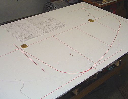
First a line was drawn lengthwise on the table to represent the Rudder Spar tube. All other measurments are taken from this line. The spar line of the rudder was located on the table so the hinges to fall in the grooves that I had previously routered out for the elevator hinges. The lines for the length and width of the rudder were then measured and drawn onto the table top, as was the rib locations and lengths.
Next, the curves were drawn using the "+" marks on the plans, a nail and string tied to the marker, as was done with the elevators. Then the wing form was used to make the long curve along the back of the rudder making sure to line up with the end of each rib.
Here is a picture of the Rudder layout lines:
The tubes were then fitted and bent to shape as before. Also, like on the elevator, the 3/8" trailing edge tube must be shimmed up 1/4" to fall along the centerline of the 7/8" rudder spar tube.
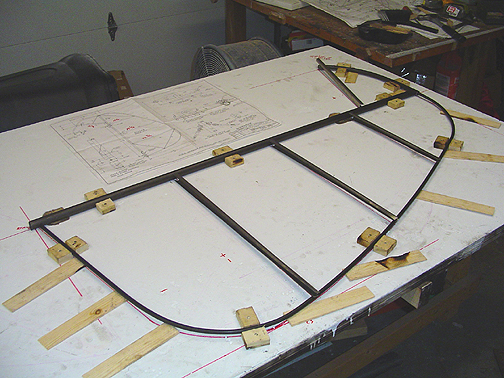
The strap hinges must be fabricated and slid onto the spar tube before welding. Also, the Rudder Horn must be fabricated and installed on the spar before welding.
The horn will be fabricated and slipped onto the rudder spar tube, but not yet welded. That will allow me to turn it to one side, and allow the rudder to lay flat in the jig. Then after everything is welded up, the horn will be properly aligned and welded in place.
The July 2003 Beartracks Newsletter had an optional engineering change for the Rudder Horn.
My plans (#682) have the outer holes of the Rudder Horn at 3 1/4" from the centerline. The engineering change for the rudder horn involves moving the holes inward 1" on each side, to locate them 2 1/4" from centerline. This will allow for better feed back pressure on the rudder and as a bonus, it will create more clearance between the toe brake structure and the firewall with full rudder deflection. I made my rudder horn with this optional change.
Here is the rudder horn with the tabs bent and the .090 reinforcing washers ready to be welded on each end:
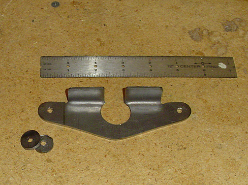
These washers were just cut from the .090 sheet and rounded off on the grinder and then belt sander. The tabs on the rudder horn were trimmed down as in the plans and the washers were welded on to the rudder horn. To keep them aligned for welding, a 3/16" bolt was slipped in the hole.
On thing to note here, the washers are not welded full circle. Only weld them on the outer half and do not weld across the face of the rudder horn (see picture below). It is thought that welding across the Rudder Horn creates a stress area. The plans show the weld as seen below, only along the outer edges of the washers.
Click here to go to Rudder page 2