May 7, 2005
The trim tabs for the elevators were made during elevator construction. Now it's time to make the Trim Tab linkage for the elevator trim tabs. My system will be slightly different than most, in that I will be using an electrically driven servo to move my elevator trim tabs. I already had a servo left over from a previous project so I figured "why not?"
The entire elevator trim linkage system was made as per the plans, but instead of running control cables up to the cockpit, I have mounted a servo in the tail section and will run wires to drive the servo. I also made my trim tab to the shorter length as was done on Prototype 2. After discussing this with Bob Barrows we decided that with the electric trim, it may be best to go with shorter tab so I can over-ride a run-away trim system, in the unlikely event that should happen. I'll show that in a minute, but for now here is how the elevator trim linkage was built.
During construction of the Horizontal Stabilizers some bushings were tack welded in place for the trim tab drive tubes. Now its time to use these bushings. I started by sliding the 1/2" drive tubes in place and then mounting the horizontal stabilizers on the fuselage. The horizontal stabilizers were properly positioned, levelled and mounted with all the attachment hardware and flying wires, struts etc. The elevators were also installed.
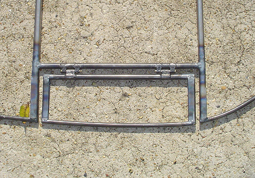
Here is a picture of the trim drive horns in place:
At this point, the holes attaching the horns to the torque tubes have not been drilled yet.
Now, with everything aligned and rotating smoothly, the bushings in the horizontal stabilizers were fully welded. As might be expected, this stopped the free rotation of the trim torque tubes.
Everything was taken apart (requires one of the Horz. Stabilizers to be removed)
and the bushings were cleaned out with a dremel tool fitted with a small
diameter drum sander. The bushings were well greased and the torque
tubes were re-assembled. The horz. stab was reinstalled. With everything
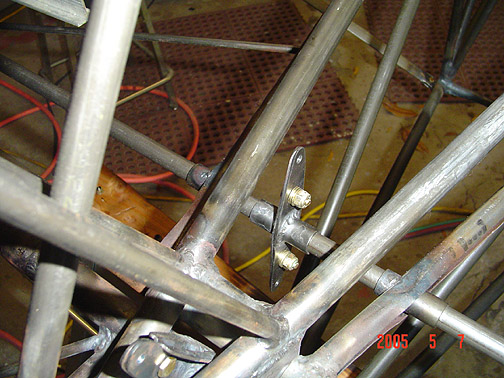
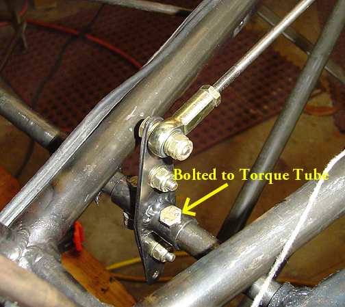
freely rotating, the horns were drilled and bolted to the torque tubes as
per the plans:
As previously stated, I have decided to control my elevator trim tabs via
an electric servo. Here is picture of my
set-up: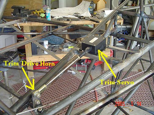
The Servo is a Mac 8A. It has 1.2" travel, is rated for 40 lbs. of thrust and only weighs 4 oz. It is a jackscrew design and has positive lock when no electricity is applied to it. I also have a small trim tab position indicator that will be mounted on the instrument panel. The servo will be controlled by buttons on the control stick grip. This allows me to control the trim tab without having to ever take my hands off the control stick or throttle.
Here is another view:
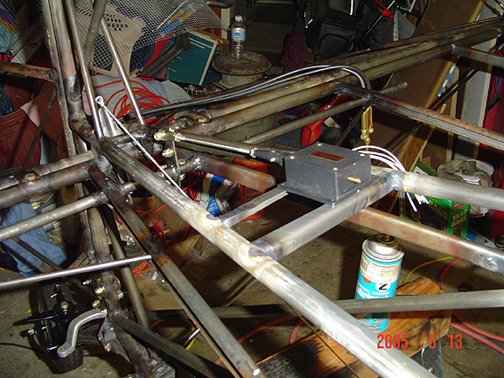
The cross pieces that the servo will be bolted to are simply some 4130N .050 plate that is bent into 1/2"x 1/2" angle and welded in between the top longerons.
As you can see in the above picture, the trim horns are located 3/4" off center to allow clearance for the elevator cable. I went ahead and ran a white string from the elevator horn down to the bottom of the fuselage at station "F". This simulates the upper elevator cable and allows me to check for proper clearances between the elevator cable and the trim tab drive components.
Click here to go to Elevator Trim Linkage page 2
Click here to go to the Tail Index page
Click here to go to the Home Page