At the aft end of the cowl where the hot air exits, we will make a lip that will cause a venturi effect and enhance the low pressure area. This will create a better flow of cooling air through the engine.
I've seen a couple of variations of the aft end of the cowl including movable cowl flaps, and various flanges both straight and curved. Usually on the ones I've seen that have a lip or flange, the lip is at a near 90 degree angle to the flight path, which in my opinion creates a turbulent air flow and lots of drag. Mine will slope back at about 45 degrees.
I have decided that I want a curved piece with about a 2" lip that starts at one side of the fuselage tunnel, curves around and ends up lined up with the other side of the fuselage tunnel. Sort of a big half of an oval shaped circle. I also want the flange or lip to slope back at about a 45 degree angle for smoother air flow. Making a piece like this is a bit of a challenge, so I asked my friend Mickey Whittenburg, who is an excellent metal craftsman to help me.
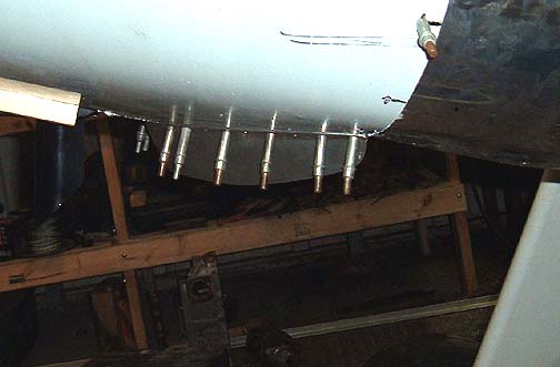
Here is a side view of the lip after trimming and tapering the sides a bit:
The only thing left to do to make a cover for the filter airbox and mount
it to the bottom cowl.The cover was installed with aluminum pop rivets:
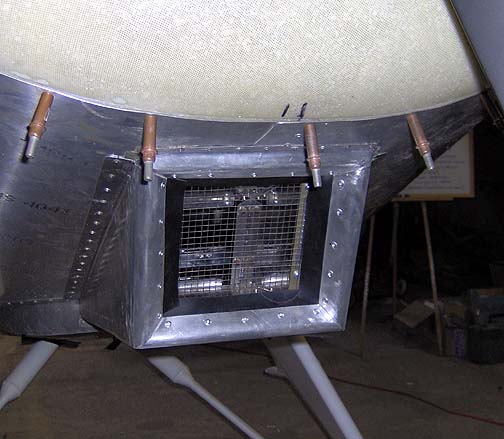
The rubber strips were sandwiched between the flanges and a 3/4" wide strip
of aluminum on the back. They were installed with about 7/8" of the
rubber exposed.
Here it is with the filter element and holder installed :
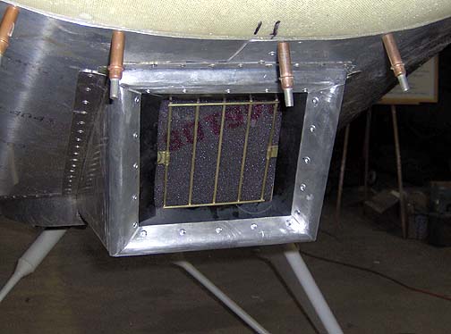
To access the 2 screws for the filter holder, you just pull the rubber strips
back.
This takes some time to make and get it right, but I think it's a very elegant way to handle the carb air intake and filter.