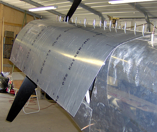
With the hinge clecoed in place on the door, we can now attach the door to
the top cowl piece and see what kind of fit we have. Here is the initial
fitting:
Starting to fit nicely but needs just a bit more tweaking. At this point the door was removed, rolled a little and replaced several times until I got a good fit. I found that even with my best efforts, I still got a bit of spring-back at the bottom, but that's okay, the camlocks will hold it shut.
Once the door was fitting nicely, it was final trimmed to allow it to fit inside the groove of the nose bowl flange and to allow a 1" overlap at the aft end. It was trimmed for a 2" overlap at the bottom.
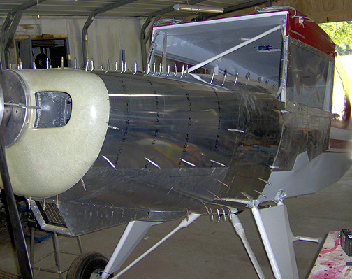
The location of the cowl fasteners (Camlocks) was determined and holding
the door down tightly, the holes were drilled and clecoed for now. Here
is the completed cowl door on the pilot's side:
Engine Cowl
Completed: July 27, 2007
Total Time: 48 hours
Click here to go to the Firewall Forward Index page