Engine Cowling page 3

So, with the carburetor airbox not on the airplane centerline, I now have two choices:

Option 1 - Build the air intake tunnel to be off center. In looking at the pictures of Proto1, which has the same engine as mine, it looks like Bob exercised this option.  See picture of Proto 1 here:

Picture courtesy of Russ Erb's CD

Option 2.  Make the opening in the bottom cowl about 3" wider than needed and make a cover for it. Then build a new air intake tunnel that angles over from the carb airbox to the centerline and install the filter there.  

Option 2 is a LOT more work but worth it in my opinion. So I opted for option 2.  

The opening in the cowl for the air intake tunnel was measured out and rough cut.  Now we can get to the carb airbox and start manufacturing a ram air intake tunnel that will go between the filter bracket (at the front) and the carb airbox (at the rear).

We started by making a cardboard template of the air intake tunnel sides.  Once we were happy with the shape and length, the template was used to trace out the shape onto some .025 2024 T3 aluminum.  1/2" flanges were bent inward on all four sides. With two of these made (opposites), we now have our tunnel sides. These were then attached to the carb airbox with four screws as shown here:

These are little too long and were shortened a bit to allow the filter bracket to ride inside the hole in the cowl.  Everything should clear with 1/2" to spare. The right side had to be about 1/4" longer than the left side to hold the filter bracket square and parallel with the nose bowl flange.

Next the filter bracket was attached to the front of the air intake tunnel side pieces. Caution: Before installing the top and bottom of the air intake tunnel, make sure the air filter is located where you want it and is level and square (parallel with the nose bowl flange). Once you install the top and bottom pieces of the tunnel, the box is locked in at that point, and there will be no adjusting it.

With the filter bracket installed, the air intake tunnel was positioned so the filter bracket was centered in the cowl. A "C" clamp was used to hold it in position. The bottom cover for the tunnel was then cut to fit and clecoed in place as shown here:

The front and rear of the bottom piece has a 1/2" flange bent at the correct angle to rest against the filter bracket (at the front) and the carb heat box (at the rear).

With the bottom in place, the positioning was re-checked and then the top piece was fabricated and clecoed in place:

At this point the box is solid and can be removed from the engine to allow drilling of the remaining holes.

The air intake tunnel was removed from the carb airbox and all edges were smoothed and holes deburred.  Since you can't get to the back of the filter bracket to tighten nuts, some plate nuts were installed on the back side of front flange of the intake tunnel.  Then the filter bracket can simply be attached with 8-32 machine screws. 

Here is the air intake tunnel ready for riveting:

The tunnel box was riveted together using 1" spacing and stainless steel pop rivets for strength.

After riveting, the air intake tunnel was re-attached to the carb airbox and filter bracket was re-attached.  Here it is mounted on the engine:

As you can see, my air filter is nicely centered on the cowl.  You can see the pipe hanging down from the carb air box, showing how off-center it is. Note: The picture above is tilted slightly (sorry about that) so the filter bracket looks a little off.  In real life, it's perfectly centered and level.

One important thing to note is that there at least 1/2" clearance all around, which is pretty important considering how much these Lycoming engines shake, rattle and roll during start-up and shut down.  At this point, you might be wondering about the big ugly hole in the cowl that the air intake tunnel sits in.  Stay tuned, we will be building a cover that will not only give it a give it a nice finished look, but will tie the two halves of the bottom cowl together.

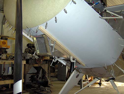
Here is the side view of the bottom cowl and air box tunnel at this point:

The big hole that was cut in the bottom cowl  to allow clearance for the air intake tunnel, caused it to lose it's stiffness and it got a little saggy in the middle.  This will be fixed when we make and install the tunnel cover.  For now we just temporarily clamped some wood strips inside and out as shown in the picture above.  This holds a nice straight line on the bottom cowl for the next part of the fabrication process.

Click here to go to Engine Cowl page 4

Click here to go to the Final Assembly Index page