Engine Cowling page 1
Started May 19, 2007
The first step in the engine cowling fabrication process, is to locate and
position the nose bowl. You can purchase your nose bowl from Bob Barrows
by going to this website:
http://bearhawk-fiberglass.tripod.com/
If you have purchased a nose bowl that is a split, start by assembling the
two halves and drilling and clecoing them together. The nose bowl,
prop spinner and prop must be installed to get this set up properly.
The nose bowl must be positioned in its final place and then firmly clamped
in position so it can't move during the fabrication process of the engine
cowling. The nose bowl should be spaced to allow a 1/4" to 1/2"
gap between the nose bowl and prop spinner. To space mine at exactly
1/4", I used some wood blocks as shims. The spinner plate is 1/2" deep
so I used some 3/4" thick wood as a spacer between the spinner plate and
the front of the nose bowl as shown here:
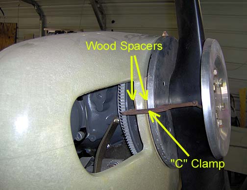
Note in the picture above, the nose bowl has been positioned so the top
is slightly low where it meets the spinner. This is to allow for engine settling.
With new motor mount rubber spacers, you can expect the engine to settle
and move down about 1/8" or so after you have flown for a few hours. If
you align the nose bowl to line up with the prop spinner at the top, the
nose bowl will end up being too high after the engine settles.
The top "C" channels can be placed under the firewall flange and under the
nose bowl flange because there will be a hinge sandwiched between the channels
and the top skin. The hinge acts as a spacer and brings the skin flush
with the boot cowl and the outside edge of the nose bowl.
Next, the same size "C" channels were made for the sides. These will
be installed low enough to have good access to the engine bottom spark
plugs:
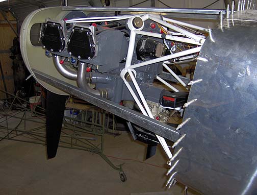
Make sure that you position these side "C" channels to be parallel
with the bottom of the side windows and tops of the cabin doors. This
will give you nice lines that are parallel and flow nicely, especially when
you start laying out your stripes.
Click here to go to Engine Cowling page 2
Click here to go to the Final Assembly Index
page