Wing Rib Formblock
Started August 17, 2003
One of the things about building a plans built, from scratch, airplane is that you have to build a lot of jigs. Jigs are simply tools that are built to form, shape, weld and/or drill the various components and allow you to make several copies of the same component and have them all come out consistently identical in size, shape and hole placement.
The first jig made was the formblock for the wing ribs. With the form block, I'll be able to make the wing ribs all identical in size, shape and all of the tooling and lightening holes will be located in the same spot on every rib. Each rib is hand formed by first clamping an aluminum blank that has been cut to the proper shape, between two formblocks, then hammering the edge of the aluminum blank over the edge of the formblock to create a flange. If every flange is formed in the same manner, using the same formblock, the ribs will be identical in size and shape. This is very important to create smooth, consistent wings that are identical from left to right.
Constructing identical sized ribs is important, as varying sized ribs would make for a wavy wing at minimum and could possibly lead to a plane with very poor flying characteristics. The formblock will allow repeatable, identical ribs for the wings, ailerons and flaps.
There are a lot of opinions on the type of wood to make the formblock from. Everyone agrees that soft woods like pine or fir are not acceptable because they would not stand up to the repeated hammering necessary to form the multiple ribs. Several have made their formblocks out of a material called MDF manufactured wood. MDF stands for Medium Density Fiberboard and comes in 4 x 8 sheets like plywood. Many have used the hardwoods like Oak, Mahogany, Ash or Birch. I found that these are hard to find in the thickness needed and are expensive. The formblock should be at least 3/4" thick with 1" being even better. I have also heard that these woods can change size and/or shape with humidity changes. MDF will not and when drilling it you don't have to worry about the drill bit following the grain and getting off center.
After much research and pondering, I chose the MDF for my formblocks. They had it at the local Home Depot for about $18.00 for a 4' x 8' sheet of 3/4" thick.
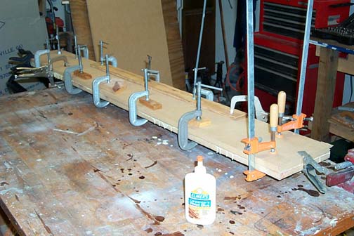
Two pieces of the MDF were glued and clamped to form one piece with 1.5" thickness.
After talking with my EAA tech counselor, Mickey Whittenburg, who has scratch built several airplanes and even designed his own, I decided to just go with just the original 3/4" thickness. That should be plenty thick enough for the 9/16" flanges that must be formed on the edges of each rib.
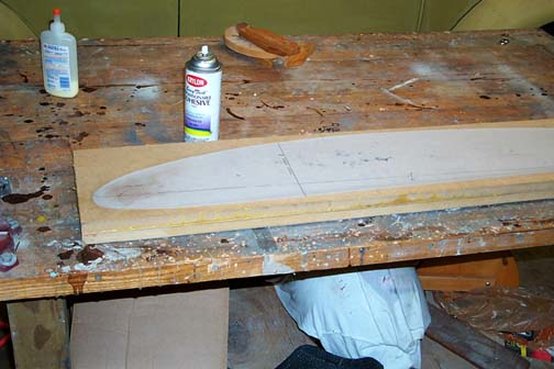
The plans came with a full sized drawing of the wing rib on mylar material, kind of a semi opaque plastic, so it will hold up. On the drawing is marked the hole locations, spar locations and the outline of the wingform. Taking some scissors the wingform was carefully cut from the mylar drawing being careful to cut to the inside of the line. The drawing was then glued to the MDF using some repositioning spray adhesive that was purchased at the local hobby store.
Note: In the above picture you can see that the mylar wingform drawing is glued to the double thick MDF. I later changed my mind and went with two pieces of MDF single thickness. The reason for two formblocks being made will be explained shortly.
With the Mylar wingform drawing glued down nice and flat, with no creases or wrinkles, a fine tipped felt marker was used to trace the outline of the pattern onto the MDF board. Each hole location was transferred by using a sharp nail and hammering a small hole through the mylar drawing and on to the board. The spar locations were also marked. Pattern was removed and the same thing was done on another piece of MDf board so I had two.
Using a Bandsaw, the formblocks were carefully cut staying just to the outside of the line. Next a table top sander was used to carefully sand the edge of each formblock to the line. The formblocks were sanded until just a faint line was barely detectable. Here is a picture of the formblock and the belt/disc sander used to finish it to the line.
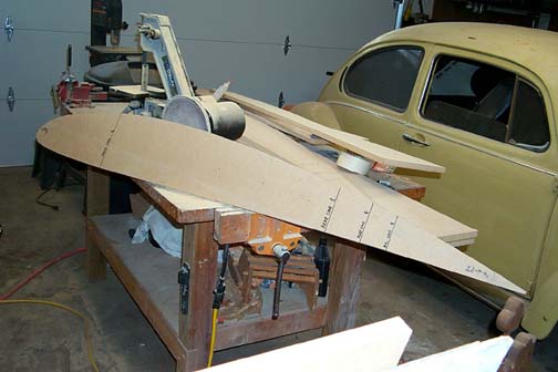
In the above picture, you can see my other project.
Our '73 VW bug, that I am restoring.
As previously stated, the rib blanks are cut from sheets aluminum and the rib flanges are then formed by bending them over the edge of this formblock using a dead blow hammer or rubber mallet. The finished flanges of the ribs should end up at a 90 degree angle to the rib web. One of the attributes of bending aluminum is that it tends "spring back". Meaning that if you form the edges of the jig at a 90 degree angle, then bend the aluminum over it, no matter how much you hammer it, the aluminum will spring back a small amount and the bend will result in a less than 90 degree angle (about 80 to 85 degrees).
To account for "spring back" while forming the ribs, the disc sander table was set up to have a 6 degree angle from the disc. This resulted in the edges of the form blocks having a 96 degree angle edge instead of a true 90 degrees. This will result in a net effect of closer to the required 90 degree angles (after spring back of the aluminum) when the flanges are formed. This is why 2 formblocks were necessary. You have to make left wing ribs and right wing ribs. This means that 1/2 of the ribs have the flange facing left and 1/2 of the ribs have the flange facing right. (left wing, right wing). Therefore, two identical formblocks were made, each with the edge angled at 96 degrees but in opposite directions, one left and one right.
It is very important in aircraft quality construction that the bends in aluminum or steel have a radiused corner. The corner of each bend must have a radius rather than a sharp bend. This will prevent cracking later as the piece is subjected to repeated vibration, loading and unloading, bending etc. With a sharp cornered bend, eventually a crack will develop from work hardening of the piece. The minimum radius for various thicknesses of aluminum are outlined in 43-13-1B Acceptable Methods, Techniques and Practices-Aircraft Inspection and Repair. There is also a wealth of other information contained in the document which is required reading in my opinion.
Edges of the wing rib formblocks were radiused to 1/8" which is more than enough for the .025 and .032 aluminum ribs. Remember, this is the "radius" so a 1/8" radius would be the equivalent shape of a 1/4" drill bit. The radius of each edge of the formblocks were sanded using sandpaper and a sanding block to create a nice rounded edge to bend the aluminum over.
Once the two formblocks were exactly the same and edges were angled properly, they were clamped together with their edges perfectly aligned and all of the holes were drilled as per the mylar drawing. This was done on a drill press to assure perfectly perpendicular holes all the way through both formblocks.
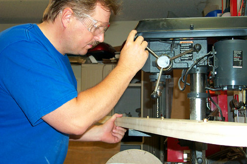
As each hole was drilled to 1/4", a bolt and nut were placed in it to keep proper alignment before drilling the next hole. These holes are jigging (or tooling) holes and some are future lightening holes. These holes are later transferred to the aluminum rib blanks and will be used to align all of the ribs for future cutting and or shaping, and also when they are attached to the main and rear spars. This assures proper alignment and consistency. The lightening holes will be later cut out to a large diameter ( some 5") on the ribs. The lightening holes serve two purposes. They reduce weight without reducing strength and they allow you to get your hands in there for riveting the wing skins on.
Completed August 22, 2003
Total time: 8.5 hours
Addendum (October 06, 2003): After forming all of the ribs that get hammered on the formblock, I can attest to the fact that the MDF held up extremely well. There are no signs of wear anywhere on the MDF. I highly recommend it to future builders.
Click here to go to Nose Ribs page 1