Started April 18, 2005
When the elevators were made, I intentionally left the spars a little extra long so they could be final trimmed when mounted.
The Elevator Horns are drawn full size on the plans and again, I used the 3/4" steel bending block, bench vice and hammer to form the legs on the horn. These are simple to make so I will not detail it here.
The right side elevator was mounted on the horizontal stabilizer and the
spacing between the elevator counter-weight arm and the horizontal stab was
set at 1/2" This allows for 1/16" shrinkage. The elevator spar
was then marked and trimmed to the correct length to allow the elevator horn
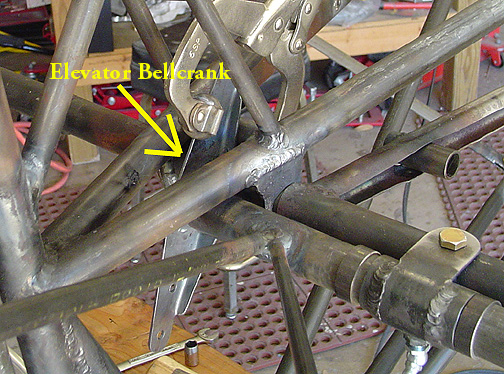
to land centered between the fuselage top longerons. The elevator horn
was then clamped to the cross tube (which acts as the up-stop for the elevator)
as shown below:
This represents where the elevator horn should be with the elevator in it's most up position which is 30 degrees up elevator.
Next, the right elevator must be positioned at 30 degrees up angle and the
horn welded to the elevator spar.
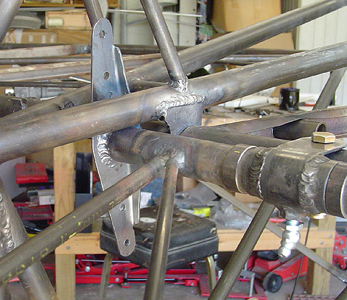
The elevator and horn were removed and the horn was welded to the elevator
spar. The right elevator was then re-installed:
With everything centered, weld the hinge keeper rings on either side of the
inner elevator hinges to the elevator spar. Don't worry about spacing,
just butt them up to the hinges and weld them. The heat from the weld will
shrink the rings a bit and create an adequate gap. When you weld these,
you will find that your once freely rotating elevator hinges, will now be
quite stiff. Don't worry about it. Let them cool and grease them.
They will loosen back up again. I found that greasing them while
they were still a little warm to the touch, helped spread the grease around
nicely. Go back and re-grease them after they cool completely.
Elevator Stops
All flight controls should have positive stops that limit the control surface's
travel. The elevator has an up-stop and a down-stop. They are
both in the form of cross tubes welded in between the top fuselage longerons.
The up-stop is the tube just forward of the elevator horn and the down-stop
tube is aft of the elevator horn. Here is the elevator in the down
position with the horn against the down stop cross tube:
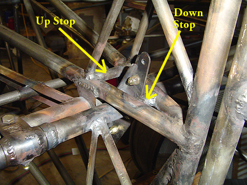
The limits of travel should be set at 30 degrees up and 20 degrees down.
Mounting the Elevators
Completed: April 20, 2005
Total Time: 8 hours