May 19, 2005
The basic support frame of the Control Stick Assembly is made up of a piece of 1 1/8" steel tube (4130N) and some plate steel (4130N) ends. Most all of the rotational parts in the control stick assembly, are a simple tube in a tube bearing system similar to that used as the Elevator Hinges but instead of grease fittings, they have oil holes.
The control stick mounting brackets were made out of some .062 steel sheet
(4130N). A template was made by using some carbon paper and poster
board and tracing directly from the full size drawing in the plans. Make
sure that you add the 5/16" flange on each side. The shape was then
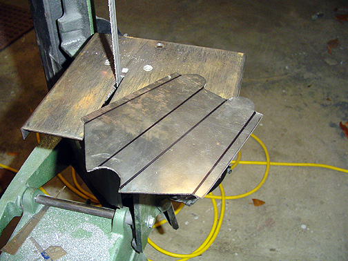
transferred to the steel plate and cut out using a bandsaw. Here is
what it should look like before bending:
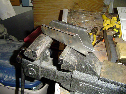
The bend is a little complicated but doable. The two bends in the middle create a "U" shape and the 5/16" flanges bend in the opposite direction. I once again turned to my trusty 3/4" bending block and bench vise to do this job.
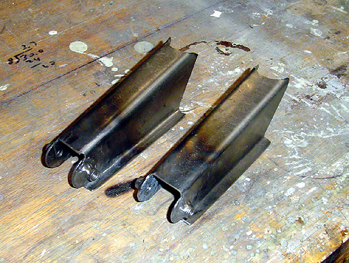
Here is the completed control stick mounting bracket minus the holes for
the control stick:
The plans call for an .060" thick washer (3/4" diameter) and short
piece of 3/8" tube to be welded on each side of the mounting bracket.
Here are both control stick mounting brackets ready to be welded to the support
tube:
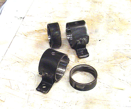
Here are the finished bearings complete with oil holes:
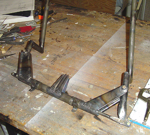
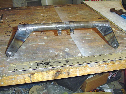
Here is the control stick support assembly after assembly and welding:
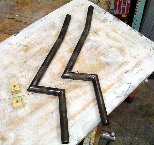
The control sticks are made from some 7/8" tube. The pattern was laid out on a piece of plywood. The angles were copied from the drawings using a protractor.
Here are the pair of control sticks:
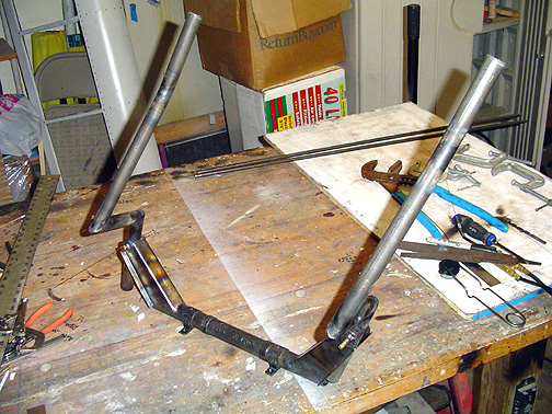
Here is the control stick assembly with the sticks installed:
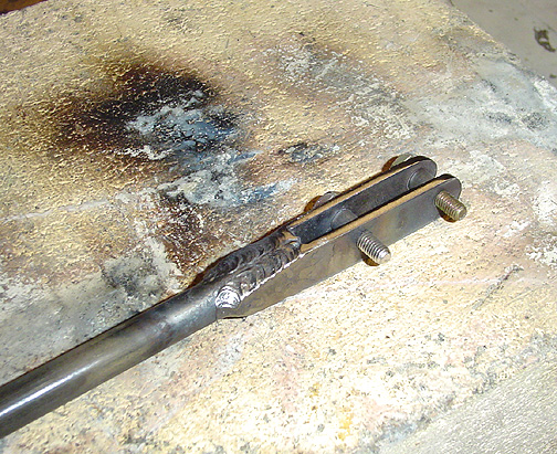
Here is the end piece welded up and the ends of the fitting have been filed
smooth:
Here is the completed control stick assembly ready to be fitted to the fuselage
frame: