The Rudder Cable Fairleads are installed in the lower corner of each Station location starting at station "C" and going back to Station "F". The cables then run directly to fairleads at station "H". Finally, the cables run from the fairleads at station "H" ,directly to the rudder horns.
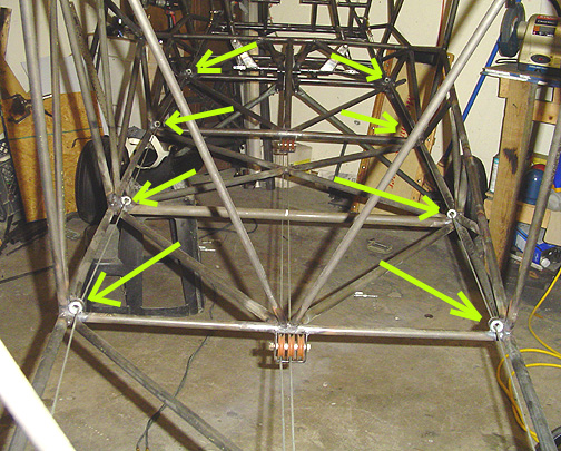
Here is a view looking forward from the tail. The Green arrows show
the fairleads (in order) at stations F, E, D and C:
Here are the fairleads at station "H":
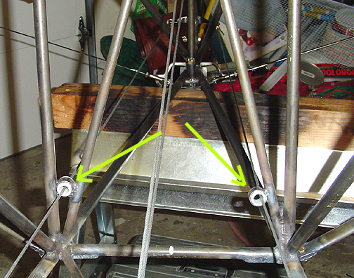
Note that these are raised a bit off the bottom corner. This gives you the most direct run to the rudder horn rather than making the cable bend so far.
The adjustment of the rudder pedal cables should be done to allow for adequate clearance of the master brake cylinder from the firewall diagonal tubes. The rudder pedals tilt aft away from the firewall. You will need approximately 1.5" of travel at the rudder cable drive, from neutral rudder to the stop. In my case, with the rudder pedal assembly being installed at 4" from the firewall, the rudder pedals had to be tilted back quite a bit to allow full travel without the brake cylinders hitting the diagonal tube of the firewall.
To test the feel of it, I rigged up a piece of plywood to act as a temporary seat and a piece of aluminum sheet to act as a temporary floor. I then got in the cockpit to try out the pedals. To me, it seemed like they were just tilted back too far and with my heels on the floor, I kept hitting the brake pedals with my toes. I read in the Beartracks that Proto 2 had its rudder pedals at 5" from the firewall. I decided to reposition mine to be the same.
To re-position the pedals, I added an additional piece of .062 steel plate to the aft side of the first piece and butt welded it to the old one. It was also welded to the longeron and diagonal tube. Of course, this was done on each side. I ended up putting a flange on the new piece to help stiffen it. I was then able to move the pedal assembly back about 3/4".
Here is the new set-up with the rudder pedals now positioned at 5" from the
firewall:
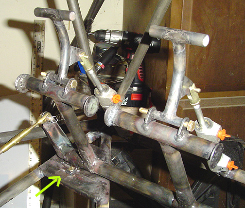
The green arrow at the bottom points to the new addition to the mounting plate. I like this set-up a lot better and my feet no longer ride the brakes with my heels on the floor.
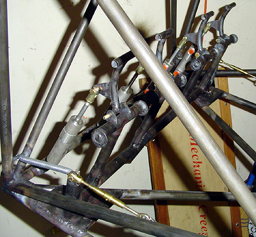
Here is the completed Rudder Pedal Assembly with brakes on both sides:
Rudder Pedals, Cables and Brakes
Completed: June 25, 2005
Total Time: 37.5 hours
ADDENDUM added November 18, 2006
After some review, I have decided that I don't like the turnbuckle for the
rudder cables at the pedal. I feel this gives an opportunity for the
the turnbuckle or safety wire on it to snag in my pants leg. Mark Goldberg
placed his rudder cable turnbuckles just aft of the baggage compartment where
they can still be accessed but will be out of the way. So I modified
mine to do the same as shown below:
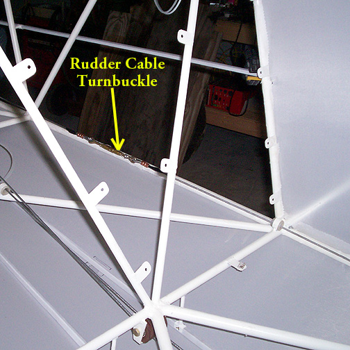
Note: As you can see, at this point I have already primed the fuselage and am starting the covering process.
The cable at the rudder pedal is attached like this:
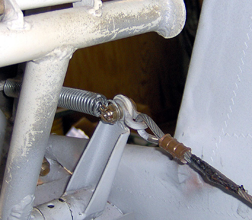
As you can see, the spring is encapsulated by washers on the same bolt as the cable shackle. It's held in place with castle nut and cotter pin.