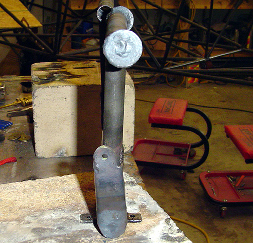
Although the plans don't show it, I have made a provision for preventing
my feet from slipping off the sides of the pedals. I simply used some
1" diameter washers and welded them to the ends of each rudder pedal, off-set
toward the aft side:
Also note in the above picture that the drive arms are not aligned with the rudder pedals but are canted forward slightly. I don't know the exact angle, but looking at the plans, it looked like the hole was aligned with the front edge of the rudder pedal up tube, so that's the way I set mine up.
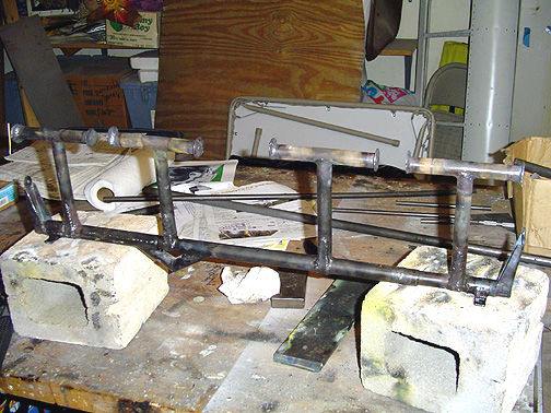
Here is what the rudder pedal assembly looks like at this point:
Now we can start the installation of the brake pedal assembly.
The Brake pedals are like miniature rudder pedals and are mounted to the top of each rudder pedal. The "up" tube of each brake pedal is curved. To do this, I copied the arc full scale onto my table top and bent a piece of 1/2" tube until it matched the arc exactly.
Here is a group photo of the 4 brake pedals:
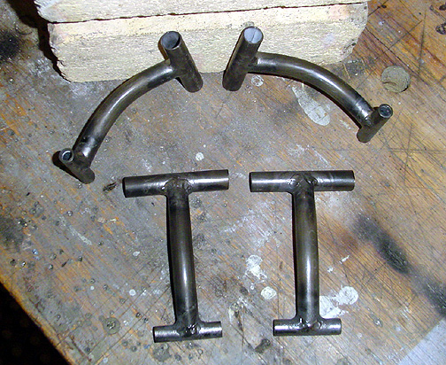
I was careful to get all the brake pedals the same length.
A couple of mounting tabs were welded to the top of each rudder pedal and
the brake pedals swivel on a 1/4' bolt. Here is the pilot's side brake
pedals as temporarily installed on the rudder pedals:
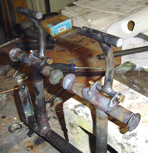
The mounting tabs are angled forward on the rudder pedals as shown in the plans.
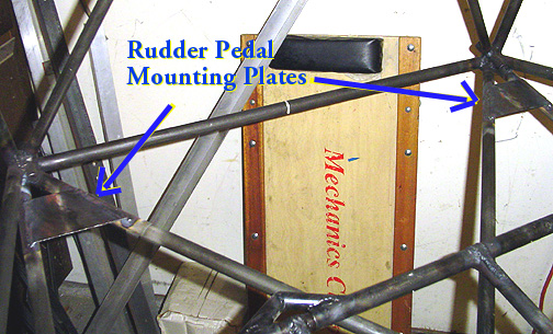
The Rudder Pedals are mounted on some .062 steel plates welded to the fuselage
bottom longerons and diagonal tubes near the firewall. Here are the
steel plates welded in place:
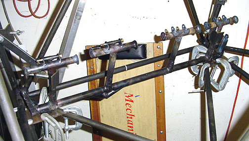
The Rudder Pedal Assembly was then clamped in place, so the holes in the
bearings could be match drilled to these mounting plates:
Click here to go to Rudder Pedals page 4