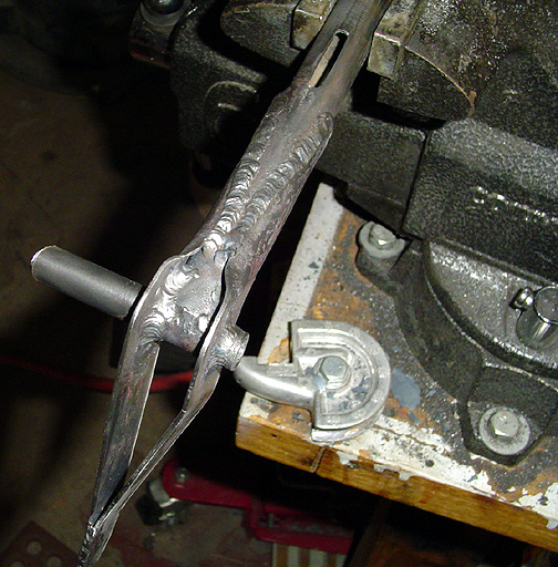
Here it is after welding:
This same treatment is done on the bottom side of the flap handle. Make sure the notch in the flap handle tube is exactly perpendicular to the drive arm tube that will act as the rotational part (axle) of the flap handle. Note in the above picture that the flap drive arm is off-set to one side at the bottom. This allows for a little better clearance of the flap cable as it passes through the landing gear strut attachment plates on the bottom of the fuselage.
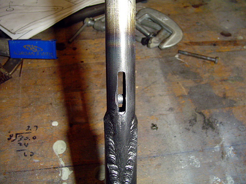
Here is a picture with the push button tube slipped inside the flap handle
tube. You can see the 1/4" steel pin that will be pushed (by
a spring) into the notches of the aluminum arc to create the various degrees
of flap deployment:
A 5" spring was slipped in first and pushes the pushbutton tube upward.
The bottom of the pushbutton tube was fitted with a piece of .062 steel
plate for the spring to push against. The steel plate was welded in place
and then shaped on the grinder until it was flush with the tube sides. The
spring pushes the tube upward (outward) which pushes the 1/4" steel
pin into the notch on the aluminum arc. When you push the button, the
tube slides back, releasing the pin from the notch and the flap handle can
rotate.
Here is a group photo of the various flap handle parts:
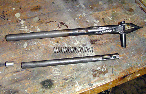
Notice that the notch in the pushbutton tube is longer than the notch in the flap handle tube. This is because it must be have room to slide back and forth to release the pin from the notch in the aluminum arc piece.
The last piece to make before mounting the flap handle in the fuselage is
the bearing that the flap handle pivot axle (the 1/2" tube) will rotate in.
A piece of 5/8" tube is welded between a couple of attachment brackets.
The attachment brackets are shown full size on the drawing and were cut using
the template method.
Click here to go to Flap Handle page 3