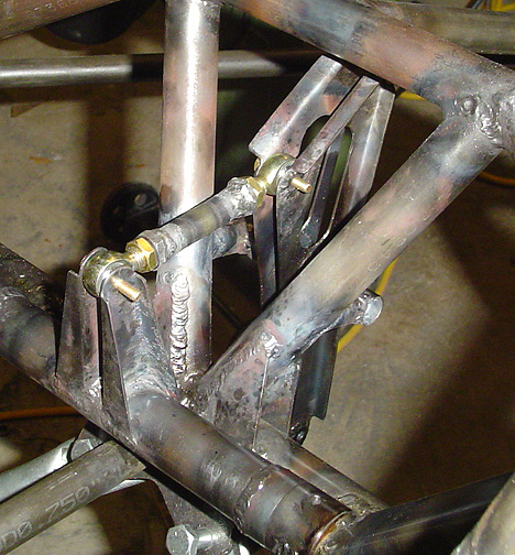
The connection between the control stick assembly and the elevator bellcrank is a pushrod with rod end bearings on each end. The pushrod has a nut welded on each end that the rod end bearings thread into and a jam nut is threaded on each end as well. I couldn't find what size rod end bearings are called for, so I just measured the plans and figured out it should be a 3/8" threaded Bearing with 3/16" bore. I used Aurora (part #GMM-3M-670) Male rod End Bearings for this application.
Here is the Bellcrank assembly in place with the push rod between the control
sticks and bellcrank:
Now we can start the process of running the 1/8" control cable from the elevator bellcrank to the elevator drive horns. The elevator cables run through a couple of "gang" pulley assemblies. One gang pulley assembly is at station "D" and the other is at Station "F"
Here is the pulley as welded to the fuselage frame at Station "F":
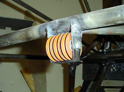
Of course the pulleys were removed before welding. To maintain proper spacing during welding, a bolt and nut were installed and tightened just enough to maintain the proper spacing.
Click here to go to Elevator Bellcrank & Cable System page 3