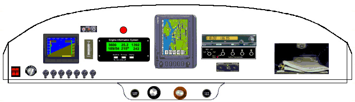
Here is a virtual layout of my panel. I used a program on the internet called Experimental Panel Planner to do this:
This is the 1st go around. I used the Dynon D10A:
From left to right the instruments are as follows:
1. Dynon D10A EFIS
2. Allen Trim indicator (above that is the remote switch for the ELT
3. Grand Rapids Technology EIS (Engine Information System)
4. Lowrance 2000C color moving map GPS
5. ICOM A200 panel mount Comm radio
6. Collins TDR250 Transponder
7. PS Engineering PS2000 stereo 4 place Intercom
8. Jockey Box (glove compartment)
The Dynon EFIS replaces Airspeed, Altimeter, VSI, DG, Artificial Horizon, Turn/Slip indicator, volt meter, and entire vacuum system. I figure on at least 25 lbs. of weight savings.
The Grand Rapids EIS replaces RPM, MAP, 4 EGT, 4 CHT, Oil Press, Oil Temp, 2 Fuel Level, Amp meter and Fuel Flow indicator. I figure at least 10 lbs. savings.
My flying is strictly VFR so I have only the moving map GPS for navigation. I always fly cross country with a sectional map on my kneeboard so that's my redundancy for navigation.
That's my plan as now - it may change as things progress, we'll see.
Here is what the instrument panel looks like installed in the fuselage:
The panel is tilted back exactly 8 degrees from vertical (98 degrees from
the bottom longeron between stations B and C ). My dynon EFIS is programmable
to account for the 8 degree panel tilt.
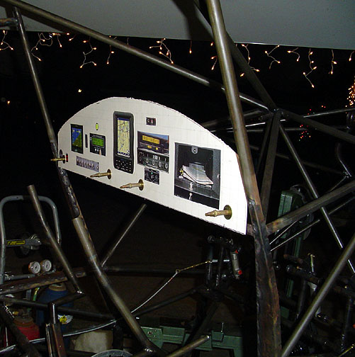
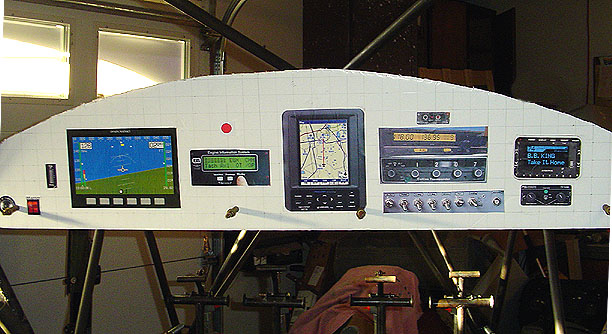
Here is a close-up on the pilot's side:
Actually, you might have figured this out already. It's really just a white poster board representation of the panel. The instruments are really just pictures printed from the internet or cut from magazines. They have been scaled to the proper size, as has the instrument panel which is 9.5" high at the center.
A couple of interesting things I found out. The Dynon EFIS has a tube 3" x 7" or so. It just barely clears the diagonal tube that runs to the firewall. To achieve better clearance, I'll slide it and the EIS engine monitor over toward the center about 1". The Jockey Box on the right side will completely interfere with the diagonal tube behind it. So its going away and I'll replace it with some built in pockets on the inside of the doors. In its place will be an XM Satellite radio receiver. My wife seems happy with the pockets in the doors (it was actually her idea). This is the panel plan as of December24, 2005. I'll look at it for a while before committing to aluminum for the real panel. Stay tuned for updates.
January 07, 2006
OK - I've been looking at this panel for a couple of weeks now and I found
that there are a couple of changes I want to make. For one thing the
Dynon D10A screen is a little small for my taste. For a couple of hundred
bucks more, I can have the new Dynon D100 which has a 7" diagonal screen
and actually has a shorter foorprint behind the panel (they did away with
the long cylinder that sticks out behind the D-10A). I have also
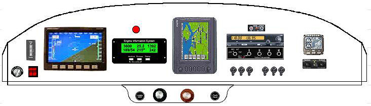
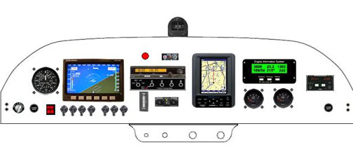
re-arranged things a bit for better clearance behind the panel. Here
is the latest version of my panel plan:
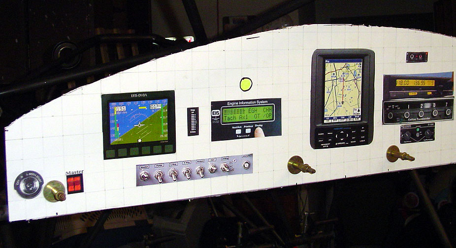
Here is a poster board version mounted in the fuselage:
As you can see, I've eliminated the map box and added an XM satellite radio on the right side. The Dynon D100 is much better for me as I do need reading glasses at this stage of my life. The new one is much larger and easy to see.
At this point, I'll wait until I get the seats installed so I can actually sit in the cockpit and reach for switches and radio knobs to see how the "feel" is. I do plan on separating the switches into groups of 3's for feel easier identification of switches. I'm also considering switching the radio/transponder with the EIS (Engine Information System) for easier reach. I could always leave the Red warning light on the pilots side to get my attention of any engine parameters that are out of whack.
The main reason I like to have the radios on the passenger side is that I like to have my wife and/or passenger handle the radio and transponder frequency switching when we fly.
December 20, 2006
WOW - Its actually been about 1 year (look at the first date on this page) since I started planning and figuring out this instrument panel.
It's finally time to put some holes in the actual instrument panel. I made the panel from 2024T3 Aluminum that's .050" thick. I bent a 3" lip on the bottom at about 98 degrees. This lip wraps around the cross tube of the fuselage and bolts to it with tabs that I welded on. Click here for some more details of the preparation of the instrument panel. When you are done, use the "back" button on your browser to return here.
Once I could mount the instrument panel in the fuselage, I started doing
some measuring and decided that the radios would most likely encounter some
interference from the diagonal tubes that run up to the top-center of the
firewall. Therefore I once again re-arranged the layout of the panel
by switching the radio/transponder with the EIS engine monitor. Here
is the final layout:
The panel along the bottom with hold the Carb Heat, Throttle and Mixture
controls.
I have decided to add a back-up airspeed indicator just to the left of the Dynon D100. I will fly it this way until I have full confidence in the Dynon and know that all the bugs are worked out. I then plan on replacing the airspeed indicator with a Trio EZ Pilot Autopilot which will fit in the same hole.
The instrument panel blank was laid out with a 1" grid using a Sharpie felt marker. The above picture was then laid out to scale with a 1" grid. The location of every instrument, radio and switch was then drawn onto the instrument panel using the proper dimensions for the cutouts needed for each item. Most of the instruments and radios show the cutout dimensions in the installation instructions. For the ones that I didn't know, I just measured the actual item.
Using drills, uni-bits, dremel cut-off wheel, jig saw and various files,
all of the holes were cut in the panel blank, carefully checking the fit
of each and every instrument as I went. Here is the panel blank all cut
out:
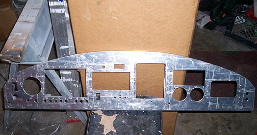
Note the switch spacing on the left side of the panel. I purposely
separated the switches into two groups (5 and 3) for easier identification
by feel.
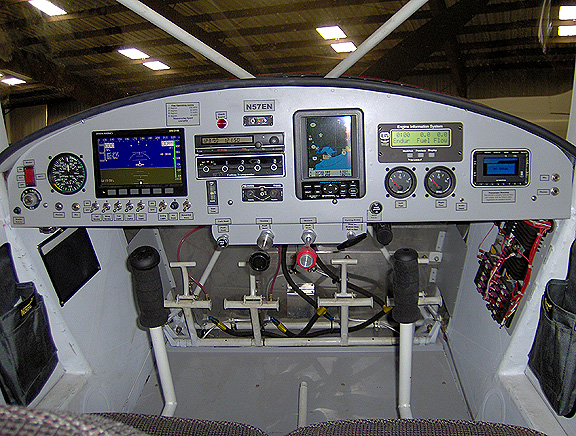
Here is the panel installed in the fuselage:
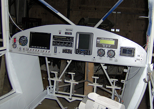
Here is the completed panel, flight ready:
Click here to go to the Home page