Engine Mount
Started 10/29/05
My Bearhawk will have a Lycoming O-360 turning the big fan out front. The
following describes the construction of an engine mount for the O-360 engine.
This is a little different than the O-540 engine. See
Russ Erb's CD for
how the Lycoming O-540 and other engines (including some auto conversions)
are mounted.
Setting up the engine alignment and making the
motor mount for it must be done with great care. Take
your time and get this part right. I spent over 8 hours just getting
the engine set up in the correct position. If you end up with the engine
canted one way or the other, it will affect how the airplane flies.
There are a couple ways to get the alignment correct - Here is how I set
up mine:
I was lucky enough to be able to borrow an old Lycoming O-360 engine case
from a friend. The engine case should be the same model as the engine
you plan to install. This engine case has some holes in it and its
"un-serviceable" but the mounts are in great shape, so it serves my purposes
well. The nice thing about doing it this way is that I won't risk burning
the paint on my newly overhauled engine.
Here is my set-up for getting the engine properly located:
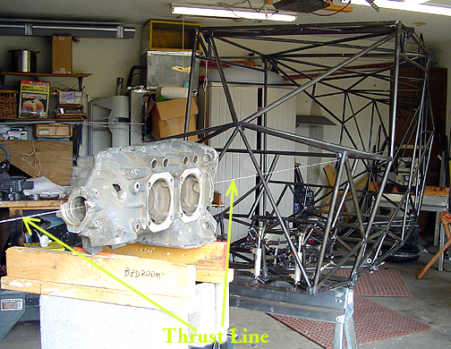
As you can see in the above picture, I ran a string from the tailspring all
the way out past the front of the fuselage several feet. This string
exactly duplicates the thrust line as shown on drawings #1 and #16. If
you do it this way, make sure the string is pulled tight so it doesn't sag
in the middle. A sturdy fishing line works well for this.
Here is the completed engine mount:
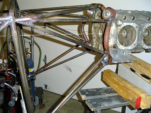
As you can see, the thrust line reference string is still in place and centered
through the engine crankcase.
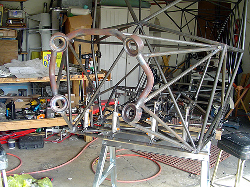
And finally . . . here is the completed engine mount awaiting the Bob Barrows
built Lycoming O-360 that I will take delivery on in January 2006.
Engine Mount
Completed: November 16, 2005
Total Time: 32 hours
Click here to go to the Firewall Forward page
Click here to go to the Home page