Started March 3, 2007
The Throttle, Mixture, Carburetor heat (and Prop if you have a constant speed prop)) control cables must be run from the instrument panel to the engine. These control cables have an outer casing of spun wire to protect the cable wire, which runs runs inside. To work properly, the cable casing must be immobilized no more than 3" from the throttle or mixture control arm. The casing is held ridged and the cable (wire) inside the control cable moves back and forth moving the throttle or mixture arm.
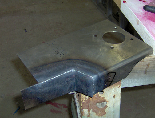
Here is the mounting bracket that I made:
Next, to save some weight, I will cut away everything that is not needed to make this bracket functional.
Here is the bracket after trimming off all excess material and cutting a
lightening hole in the top, mounted to the engine with the carburetor:
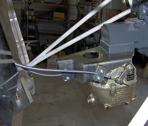
Note that the hold-down clamp is angled to achieve perfect alignment with
the throttle control arm when the throttle is closed. As the throttle
is moved to full open, the cable deflects slightly.
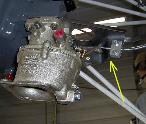
Here is the other side showing the mixture control cable hold-down clamp:
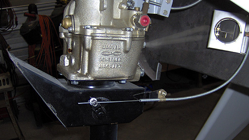
The Carb Heat control box was mounted to the bottom of the carb. The
cable was run and clamped in place with an aluminum clamp as shown here:
Now to get the control cables into the cockpit and mounted to the instrument panel.
I had really thought about getting some of the fancy firewall pass through eyeballs and finally decided that I would simply drill holes exactly the same diameter as the cable casing and just slip the cable through the firewall. Once its all mounted and stable, I will seal the pass-through with some fire-sealant.
I really didn't have room on my instrument panel for the engine controls so I made a bracket to hang under the panel. The bracket was made from some 1/8" thick 1 1/2" x 1 1/2" aluminum angle. The spacing for these controls is 3" which works out nicely
Here is the control bracket with the throttle and mixture controls
installed:
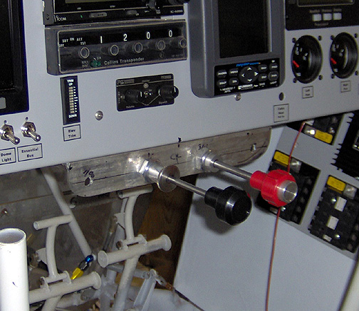
I do have some concerns about interference with the control sticks at full forward and maximum aileron deflection. If needed, I will shorten the control sticks 1". I will wait to make that determination until I have the ailerons installed and I can see how far the control sticks move at maximum aileron deflection.
Cabin heat is provided via heat coming off the exaust pipes and routed into
the cabin through a cabin heat valve mount to the engine side of the
firewall. In keeping with my idea of keeping flames and smoke out of
the cockpit, I have elected to purchase an all stainless steel heater
valve:
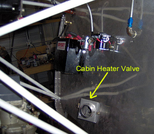
There is a 2" hole in the firewall that the hot air passes through when the above heater valve is in the "open" position.